Solderable pad fabrication for microelectronic components

a technology of microelectronic components and fabrication methods, which is applied in the direction of semiconductor lasers, instruments, record information storage, etc., can solve the problems of degraded joint alignment between components

Inactive Publication Date: 2013-10-24
SEAGATE TECH LLC
View PDF3 Cites 12 Cited by
  • Summary
  • Abstract
  • Description
  • Claims
  • Application Information

AI Technical Summary

Problems solved by technology

However, adhesive joints are sensitive to environmental conditions, such as heat, solvent, or moisture, which may cause joint alignment between components to degrade during curing and overtime.

Method used


Image

  • Solderable pad fabrication for microelectronic components
  • Solderable pad fabrication for microelectronic components
  • Solderable pad fabrication for microelectronic components

Examples


Embodiment Construction

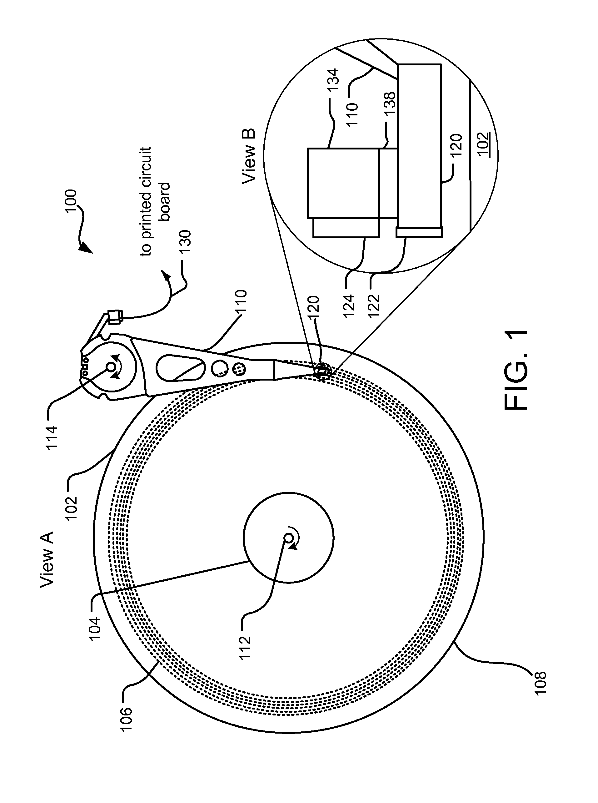
[0017]“Heat assisted magnetic recording,” optical assisted recording or thermal assisted recording (collectively hereinafter HAMR) generally refers to the concept of locally heating a recording medium to reduce the coercivity of the recording medium so that an applied magnetic write field can more easily induce magnetization of the recording medium during a temporary magnetic softening of the recording medium caused by the local heating.

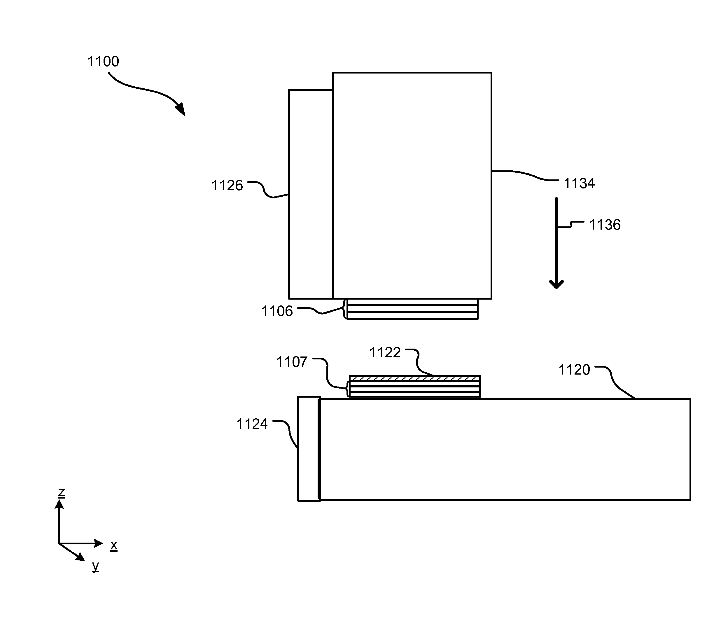
[0018]To perform HAMR, heat or a light source can be applied to a magnetic medium and confined to a bit location where a write operation is taking place. For example, a laser beam can be propagated through a waveguide and focused by a focusing element such as a planar solid immersion mirror into a near-field transducer. However, this utilizes an attachment between the waveguide and the laser that achieves a precision alignment. Additionally, the attachment mechanism may be subjected to intense heat generated by the laser. Adhesives are not ideal atta...


PUM


Abstract

Two microelectronic components can be attached by flowing solder between solderable pads patterned on interfacing surfaces. According to one implementation, the microelectronic components can include the solderable pads patterned onto first respective surfaces and other surface features patterned onto second respective surfaces. In another implementation, the solderable pads can include an adhesion layer, a diffusion barrier layer, and surface oxidation layer.

Description

BACKGROUND[0001]Microelectronic components may be bound together by adhesives. However, adhesive joints are sensitive to environmental conditions, such as heat, solvent, or moisture, which may cause joint alignment between components to degrade during curing and overtime.SUMMARY[0002]In one implementation, a method includes patterning features on a first surface of a first microelectronic component; rotating the first microelectronic component, patterning a solderable pad on a second surface of the first microelectronic component, and patterning a layer of solder on the solderable pad.[0003]This Summary is provided to introduce a selection of concepts in a simplified form that are further described below in the Detailed Description. This Summary is not intended to identify key features or essential features of the claimed subject matter, nor is it intended to be used to limit the scope of the claimed subject matter. These and various other features and advantages will be apparent fr...

Claims


Application Information

Patent Timeline
Patent Type & Authority Applications(United States)
IPC IPC(8): H01S5/022H01L23/00H01S5/023H01S5/0233
CPCH01S5/02236H01L24/03G11B5/3173G11B5/4826G11B2005/0021H01L2224/32148H01L24/05H01L24/27H01L24/29H01L24/32H01L24/83H01L24/92H01L24/94H01L2224/0345H01L2224/0346H01L2224/0347H01L2224/04026H01L2224/05082H01L2224/05155H01L2224/05157H01L2224/05166H01L2224/05171H01L2224/05181H01L2224/05184H01L2224/05187H01L2224/05644H01L2224/05664H01L2224/05669H01L2224/2745H01L2224/291H01L2224/32238H01L2224/83143H01L2224/83191H01L2224/83192H01L2224/83815H01L2224/92H01L2224/94H01L2224/05568H01L2224/05023H01L2224/83123H01L2224/8318H01L2924/12041H01L2924/00014H01L2924/12042H01S5/02375H01S5/023H01S5/0233H01L2224/03H01L2924/04941H01L2924/01026H01L2224/27H01L2924/014H01L21/78H01L2924/00H01L2224/05552H01S5/0201G11B5/1272H01S5/0237H01S5/0235
Inventor ZHONG, LIJUANSTEPHAN, JOSEPH MICHAELNGUYEN, THE NGOCLUNDE, CARL KRISTIAN
Owner SEAGATE TECH LLC
Why Eureka
Try Eureka