Temperature control of arc tube of fluorescent lamp

a fluorescent lamp and temperature control technology, applied in the direction of discharge tube main electrodes, incadescent cooling arrangements, sustainable buildings, etc., can solve the problems of slow heating of the lamp, reduced efficiency and light output, and additional mercury vapor molecules interfering with uv radiation

Inactive Publication Date: 2013-10-24
GENERAL ELECTRIC CO
View PDF1 Cites 2 Cited by
  • Summary
  • Abstract
  • Description
  • Claims
  • Application Information

AI Technical Summary

Benefits of technology

The patent describes a fluorescent lamp with a unique design that improves its performance. The lamp includes an arc tube with a light transmissive material, sealed inside an outer envelope. The arc tube has a protrusion that extends into the opening of the outer envelope, creating a cold spot. The cold spot helps to maintain the temperature of the lamp during operation. The fill includes mercury or a mercury substitute and an inert gas. The lamp's performance is improved through this design.

Problems solved by technology

When it is exceeded, additional mercury vapor molecules interfere with UV radiation.
When the arc tube is enclosed or in tightly closed or sealed fixtures, this can produce very hot lamp temperatures, leading to reduced efficiency and light output.
This may result in a slow warm-up of the lamp because the amalgam must reach a much higher temperature from room temperature compared to the cold spot temperature for the liquid and pellet forms.
Discharge lamps employing a mercury vapor pressure controlling—amalgam optimized for use in high temperature areas have the disadvantage of the longer start-up period than lamps using pure liquid mercury.
The mercury vapor pressure controlling—amalgam can maintain optimum mercury vapor pressure inside the arc tube but use of this amalgam, along with an auxiliary amalgam discussed below, leads to a long warm up time which, in some cases, can take as long as 60-180 seconds, causing low starting performance.

Method used


Image

  • Temperature control of arc tube of fluorescent lamp
  • Temperature control of arc tube of fluorescent lamp
  • Temperature control of arc tube of fluorescent lamp

Examples


Embodiment Construction

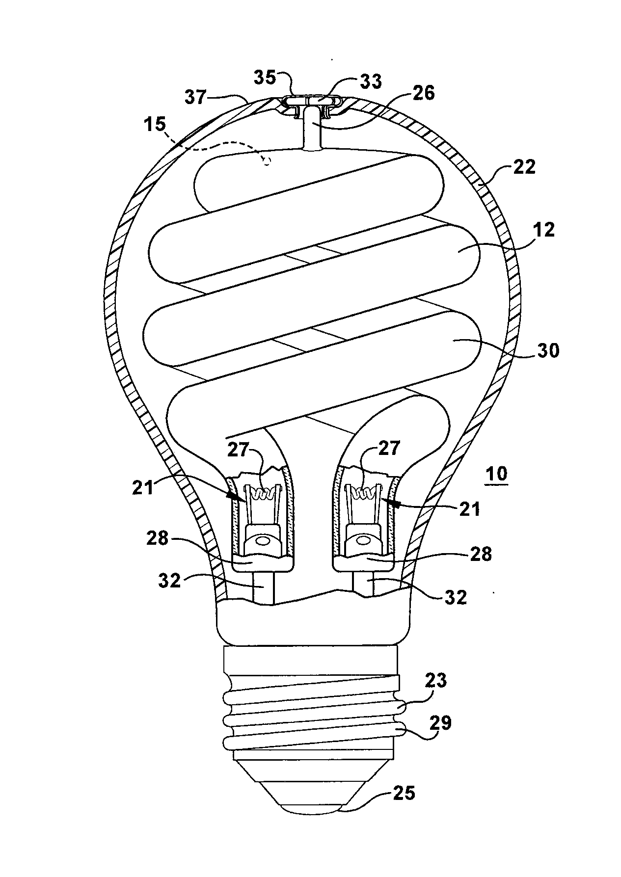
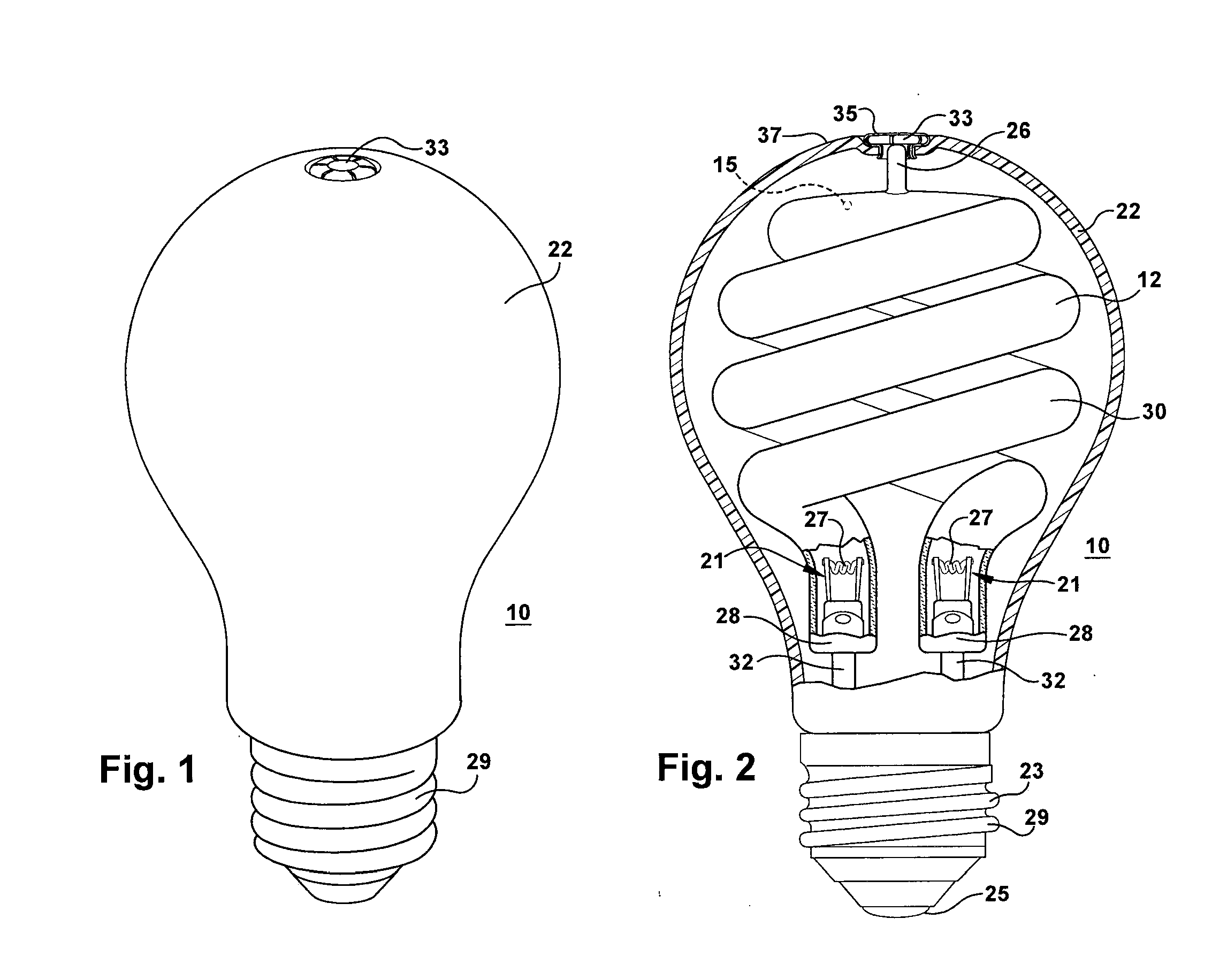
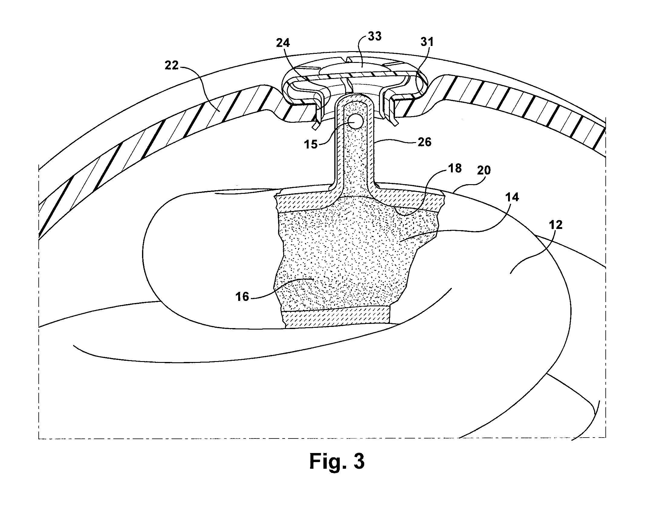
[0020]A fluorescent lamp 10 includes an arc tube 12 comprised of light transmissive material such as glass. An electrical discharge sustaining fill 14 including mercury or a mercury substitute and an inert gas is sealed in the interior region 16 of the arc tube. A dose of mercury containing alloy can be contained in a pellet 15 that alone does not control mercury vapor pressure. The arc tube has an interior surface 18 and an exterior surface 20. The arc tube 12 interior wall 18 encloses a sealed volume of the interior region 16 or discharge chamber. Electrodes 21 include filaments 27 that are disposed in the sealed interior 16 of the arc tube. The electrodes in the arc tube are electrically connected in a known manner to external electrical contacts 23, 25 at the base 28 of the lamp (FIG. 2). A phosphor layer coats an inside surface of the arc tube (not shown). The lamp is a décor style lamp having an outer envelope or bulb 22 comprised of light transmissive material such as glass d...


PUM


Abstract

A fluorescent lamp includes an arc tube comprised of light transmissive material. The arc tube can be for a compact fluorescent lamp (CFL). A discharge sustaining fill, which may include mercury and an inert gas, is sealed in the interior of the arc tube. Electrodes are disposed in the sealed interior of the arc tube. An outer envelope is disposed around and spaced apart from the arc tube. The outer envelope can take the form of a conventional incandescent light bulb, candle, globe-shape or reflector shape. The outer envelope includes an opening. The arc tube includes a hollow protrusion that extends adjacent or into the opening. This can provide the arc tube with a lower temperature near the protrusion that can approximate the temperature of the outer envelope (a cold spot). This can regulate the vapor pressure of liquid (e.g., liquid mercury) in the arc tube.

Description

FIELD OF THE INVENTION[0001]The present disclosure relates generally to a low pressure discharge lamp and more particularly to a compact fluorescent lamp in which mercury vapor pressure is controlled by a cold spot of the lamp.BACKGROUND OF THE INVENTION[0002]Inside fluorescent lamps is a vacuum and mercury gas for producing light. When the lamp is turned on an electric arc is produced along the length of the lamp between the electrodes or cathodes at opposite ends of the lamp and liquid mercury is vaporized. The electrons collide with mercury atoms and charged atoms within the lamp and then ultraviolet photons are released. The photons interact with a phosphor coating on the lamp to produce visible light.[0003]Compact fluorescent lamps (CFLs) have been used as replacements for incandescent lamps in industrial and home applications. CFLs are advantageous because they have low power consumption and a long lifetime. To maintain suitable luminous output and reduce the length of a CFL, ...

Claims


Application Information

Patent Timeline
IPC IPC(8): H01J61/52
CPCH01J61/327H01J61/33H01J61/34H01J61/523H01J61/72Y02B20/00
Inventor LUCZ, PETERBANKUTI, LASZLOTALOSI, KAROLYTOROK, BALAZS
Owner GENERAL ELECTRIC CO
Why Eureka
Try Eureka