
Differential phase shift keying system and method

Inactive Publication Date: 2013-10-24
OLYMPUS CORP
View PDF1 Cites 5 Cited by
  • Summary
  • Abstract
  • Description
  • Claims
  • Application Information

AI Technical Summary

Benefits of technology

The invention proposes a modification to rotated DPSK for binary modulation that improves performance over previous versions when using a slicer or 1-bit ADC at the receiver. This modification also makes the communication more tolerant to frequency offset, which simplifies receiver implementation.

Problems solved by technology

With many wireless devises, including IMDs, power consumption is an important parameter and system designers often want to keep the power consumption of the implantable device as low as possible.

Method used


Image

  • Differential phase shift keying system and method
  • Differential phase shift keying system and method
  • Differential phase shift keying system and method

Examples


Embodiment Construction

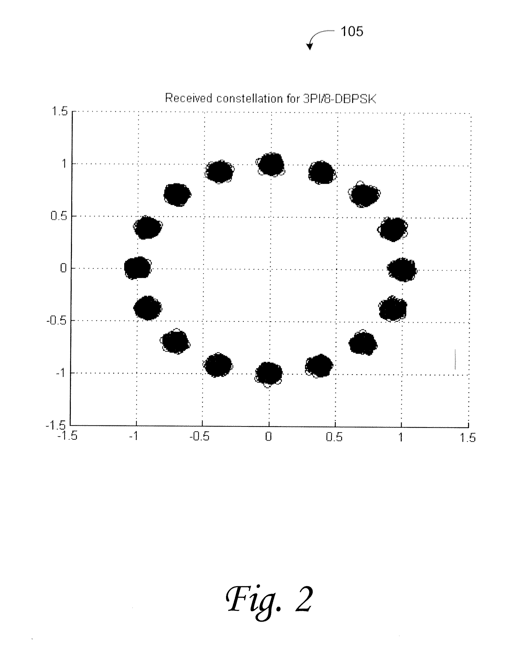
[0010]According to various embodiments of the invention a variation on conventional binary DPSK modulators is provided. In some embodiments, the scheme uses 3π / 8 rotating differential binary phase shift keying (3π / 8-DBPSK) where one symbol (e.g., a ‘0’) is transmitted by phase change of 3π / 8 radians and the opposite symbol (e.g., a ‘1’) is transmitted by phase change of −5π / 8 (or 11π / 8) radians.

[0011]Alternatively, this can be thought of as adding a constant 3π / 8 radians to the phase shift for every bit modulated according to conventional DBPSK.

[0012]In another example, assume that first and second symbols, at discrete times k−1 and k, respectively, are output by the modulator. The phase shift of the symbol output at time k relative to that at time k−1 would be a function of the modulating data, either 3π / 8 or 11π / 8.

[0013]According to embodiments of the invention, the proposed variation on rotated DPSK for binary modulation substantially improves BER / PER performance over previously ...


PUM


Abstract

A variation on conventional DPSK binary modulation schemes is provided. One modulation scheme uses 3π / 8 differential binary phase shift keying (3π / 8-DBPSK) where one symbol is transmitted by phase change of 3π / 8 radians and the other symbol is transmitted by phase change of −5π / 8 radians. Alternatively, this can be thought of as adding a constant 3π / 8 radians to the symbol angle for every bit modulated by conventional DBPSK. In another example, assume a first and second symbols, k−1 and k, respectively, are sent. Where k is the same symbol as k−1, a phase rotation of 3π / 8 radians from the kth symbol is used to represent the symbol at k−1; and where the k−1 symbol is the opposite of the kth symbol, its rotation 11π / 8 radians from the kth symbol. Other modulation schemes using other phase rotations can be provided.

Description

TECHNICAL FIELD[0001]The present invention relates generally to wireless communications, and more particularly, some embodiments relate to a differential binary phase shift keying modulation scheme.DESCRIPTION OF THE RELATED ART[0002]With the many continued advancements in communications technology, more and more devices are being introduced in both the consumer and commercial sectors with advanced communications capabilities. Additionally, advances in processing power and low-power consumption technologies, as well as advances in data coding techniques have led to the proliferation of wired and wireless communications capabilities on a more widespread basis.[0003]Implantable medical devices now routinely include wireless communications capabilities to allow, for example, wireless transmission of telemetry, such as patient or device data, from the device to a monitoring facility. Likewise command and control information can be wirelessly delivered to the medical device to control th...

Claims


Application Information

Patent Timeline
IPC IPC(8): H04L27/20H04L27/22H04W88/02
CPCH04L25/03834H04L27/2078H04L27/227
Inventor AMANULLAH, ABU S.IONESCU, DUMITRU MIHAICHU, LICHUNG
Owner OLYMPUS CORP
Learn More