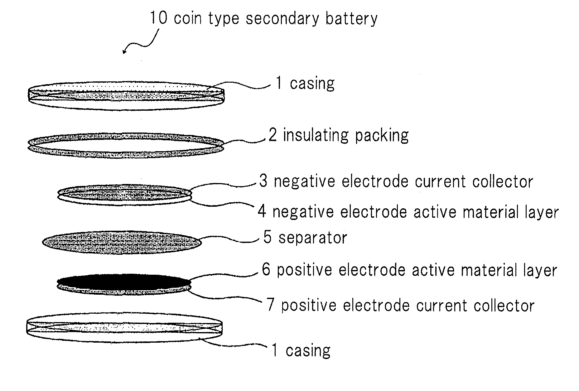
Electricity storage device
a technology of electric storage device and electric current collector, which is applied in the direction of cell components, final product manufacturing, sustainable manufacturing/processing, etc., can solve the problems of reducing the energy capacity of electricity storage, affecting the efficiency of electricity storage, etc., to achieve excellent stability and durability, reduce energy capacity, and high potential
- Summary
- Abstract
- Description
- Claims
- Application Information
AI Technical Summary
Benefits of technology
Problems solved by technology
Method used
Image


Examples
example 1
[Preparation of Positive Electrode]
[0067]To a lithium manganese composite oxide (LiMn2O4)-based material as an active material for positive electrode, VGCF (manufactured by SHOWA DENCO K.K.) was mixed as an electroconductive agent. The resulting mixture was dispersed in N-methylpyrrolidone (NMP) to form slurry. The slurry was applied on an aluminum foil as a positive electrode current collector, and dried to prepare an electrode having 12 mm diameter.
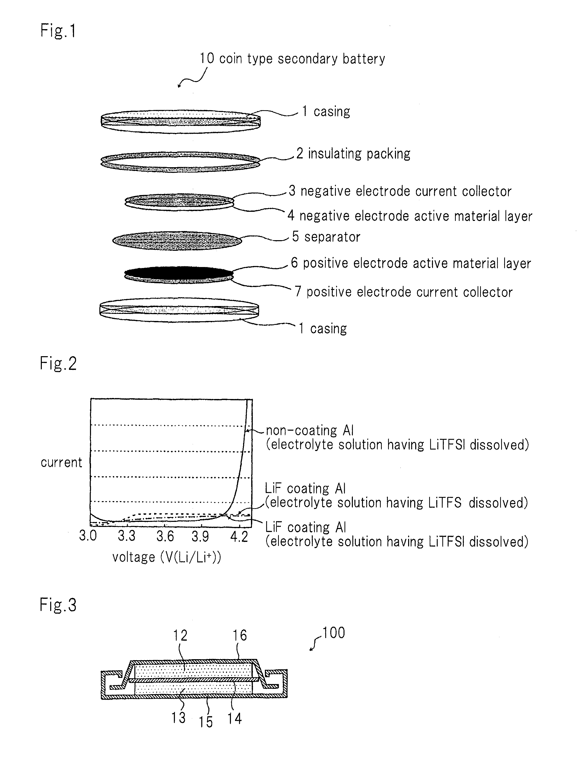
[0068]The aluminum current collector having a positive electrode active material layer formed thereon was installed within a deposition apparatus, the positive electrode active material layer was masked by a metal foil. A furnace filling lithium fluoride was heated while maintaining vacuum within the apparatus to form a film of lithium fluoride on a surface of the current collector that is not masked. The film formation was terminated based on a change in weight of crystal resonator disposed within the deposition apparatus, and a fluoro...
example 2
[0073]A coin type lithium secondary battery was prepared by the same method as in Example 1 except that a fluorolithium film formed on the aluminum current collector of the positive electrode has 200 nm thickness, and prime discharge capacity was determined. The result is shown in Table 1.
example 3
[0074]A coin type lithium secondary battery was prepared by the same method as in Example 1 except that a fluorolithium film formed on the aluminum current collector of the positive electrode has 500 nm thickness, and prime discharge capacity was determined. The result is shown in Table 1.
PUM
| Property | Measurement | Unit |
|---|---|---|
| thickness | aaaaa | aaaaa |
| positive electrode potential | aaaaa | aaaaa |
| thickness | aaaaa | aaaaa |
Abstract
Description
Claims
Application Information
 - Generate Ideas
- Intellectual Property
- Life Sciences
- Materials
- Tech Scout
- Unparalleled Data Quality
- Higher Quality Content
- 60% Fewer Hallucinations
Browse by: Latest US Patents, China's latest patents, Technical Efficacy Thesaurus, Application Domain, Technology Topic, Popular Technical Reports.
© 2025 PatSnap. All rights reserved.Legal|Privacy policy|Modern Slavery Act Transparency Statement|Sitemap|About US| Contact US: help@patsnap.com