
Small Cell Network Self-Synchronization

a network and small cell technology, applied in the field of network communication, can solve the problems of hetnet cells, poor performance, and more cost sensitiv

Active Publication Date: 2013-10-24
AVAGO TECH INT SALES PTE LTD
View PDF6 Cites 11 Cited by
  • Summary
  • Abstract
  • Description
  • Claims
  • Application Information

AI Technical Summary

Benefits of technology

The patent text describes a solution for controlling the accuracy of oscillators in various parts of a network communication system, particularly in small cells and femtocells. The traditional methods of using GPS and macrocell "sniffing" have limitations in providing accurate synchronization, as these methods require line of sight and are slow. The patent proposes a new method that utilizes an IP network synchronization protocol, but this method depends on the quality of the IP network and the performance of the protocol. The patent also describes various embodiments of a self-synchronization wireless environment that can be used in conjunction with the new method. The technical effects of the patent include improved accuracy synchronization and improved performance of the network communication system.

Problems solved by technology

Small cells and femtocells are therefore deployed in much greater numbers to supplement the cellular network and therefore are more cost sensitive.
GPS, although capable of providing an accurate synchronized time signal, generally requires “line of sight” with the satellite source, and performs poorly when the HetNet cells are primarily located indoors or otherwise obstructed from a line of sight view.
However, because femtocells and small cells are often deployed to supplement areas where macrocell coverage is poor or absent, this method does not address situations in which the femtocells and small cells are located outside the macrocell coverage area.
Finally, using an IP network synchronization protocol is not always a viable solution either, as the use of such protocols is highly dependent on Internet Service Provider (ISP) QoS, suffers from slow performance, and uses additional bandwidth.

Method used


Image

  • Small Cell Network Self-Synchronization
  • Small Cell Network Self-Synchronization
  • Small Cell Network Self-Synchronization

Examples


first embodiment

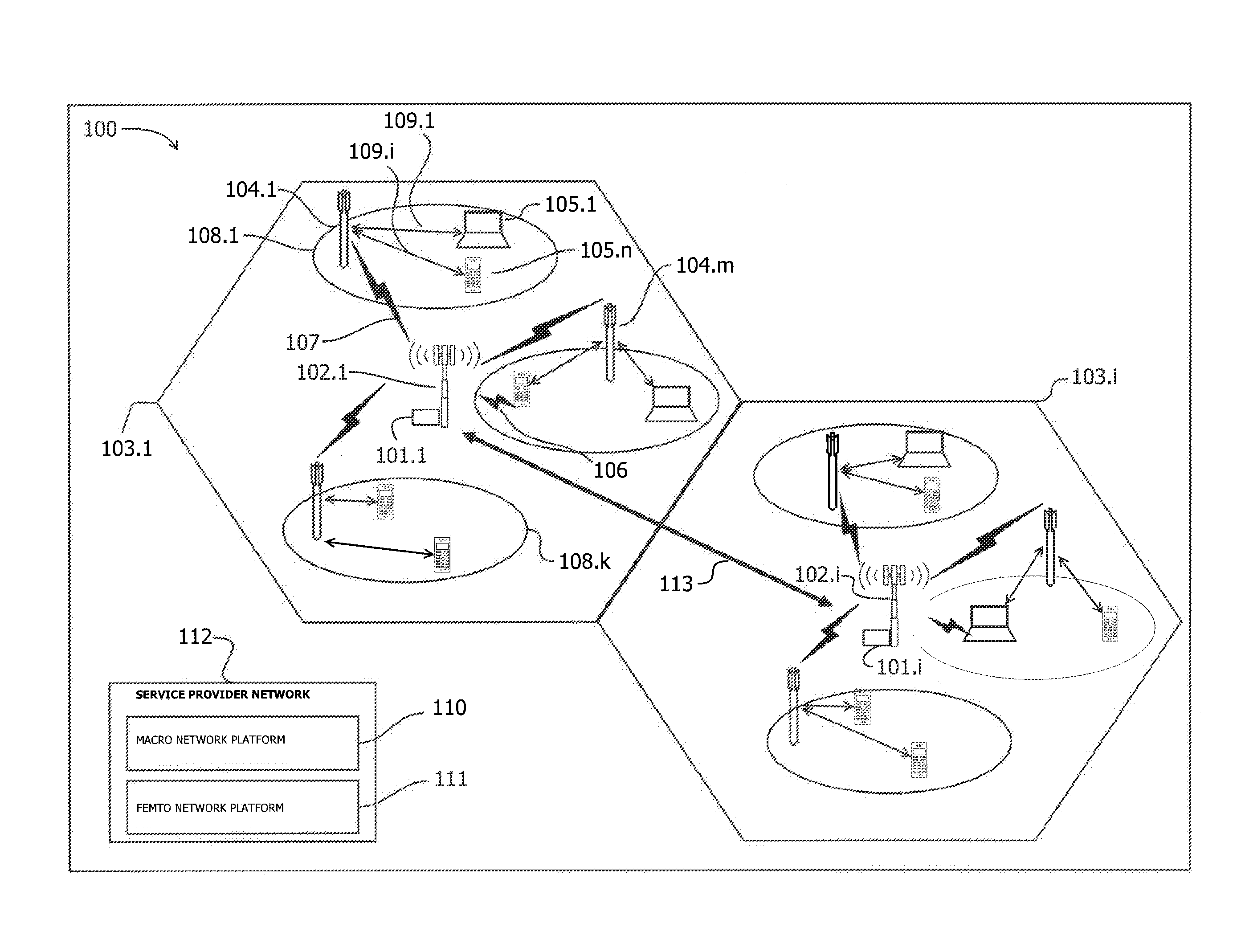
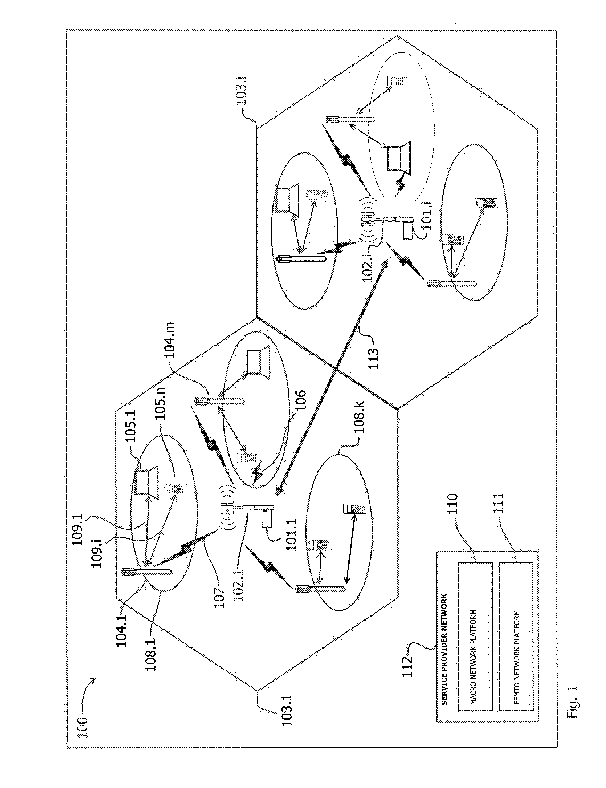
[0059]FIG. 5 illustrates an operation of a self-synchronization wireless environment in accordance with the invention. Various cell members of a wireless environment are illustrated as hexagons and constitute a wireless environment 420. For purposes of clarity, the cell members constituting 420 are illustrated as physically adjacent to one another and should be considered as having overlapping coverage between adjacent cell members. However, as previously discussed in this disclosure, physical proximity of the cell members is not required according to aspects of the invention, nor is wireless communication amongst the members needed for the SSN to function. The wireless environment 420 can be any shape or size, and cell members can have various communication ranges that are different from one another based on transmission power, amplifier gain, antenna type, number of antennas, antenna gain, etc. The wireless environment 420 can represent an exemplary embodiment of the wireless envi...

second embodiment

[0064]FIG. 6 illustrates an operation of the self-synchronization wireless environment in accordance with the invention. In this instance, center cell member 429 is the first cell in the wireless environment 420 to obtain a reliable CACL value. This can be from analysis of the convergence history log, an advantageous location allowing cell member 429 to lock onto a reliable source, or signal received through a network controller, for example. It should be noted that the center cell member 429 can also have a higher CACL due to the fact that it communicates with additional neighboring cell members, even if those members themselves do not have reliable oscillator sources, which will be discussed in greater detail with reference to FIG. 7.

[0065]Steps (a) through (f) illustrate the updating procedure associated with each cell member's CACL value throughout the convergence procedure. Similar to FIG. 5, the CACL values of each member cell are shown as propagating outward from the most rel...

third embodiment

[0067]FIG. 7 illustrates an operation of the self-synchronization wireless environment in accordance with the invention. In FIG. 7, the wireless environment 420 initially starts at step (a), in which no cell member has found a reliable oscillator source, and each CACL value is set to 0. This might be the case, for example, when a new set of femto cell access points installed at an indoor location, no convergence history has yet to be recorded, and none of the cell members have access to a macrocell network, GPS, or broadband network time information. The wireless environment 450 can represent an exemplary embodiment of the wireless environment 100 and / or the wireless environment 300.

[0068]It should be noted that crystal oscillator sources have manufacturing tolerances as previously discussed in this disclosure. Although each crystal oscillator component is manufactured to resonate at a specific nominal frequency, limitations exist in the manufacturing process. These limitations resu...


PUM


Abstract

A system, method, and apparatus to facilitate the synchronization of oscillators between members of a Heterogeneous Network (HetNet) to form a self-synchronizing network (SSN). The network members are configured to broadcast information indicative of the reliability of their oscillator. Network members attempt to look for reliable sources such as those originating from a macrocell base station or GPS. If such a source is found, the member cell updates it clock accuracy confidence level number (CACL) to indicate this. Network members also share information regarding the frequency offsets between one another. Every cell member then applies a weighted average function to determine how to update its own oscillator and CACL value accordingly. Cell members can also update their functionality, such as RF power level, in response to varying degrees of CACL values. This operation results in a convergence of all cell members to the most accurate oscillator offset value.

Description

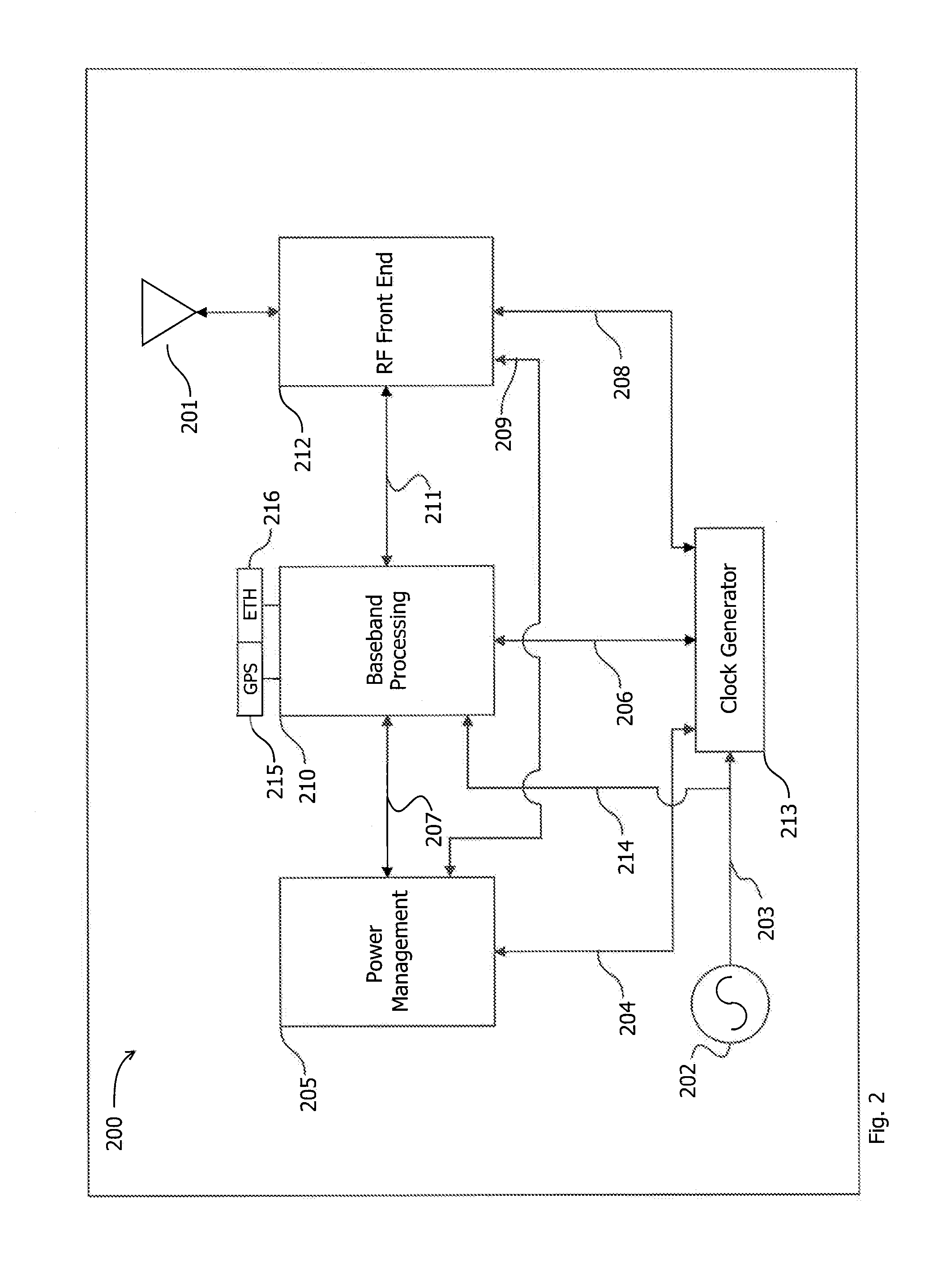
CROSS-REFERENCE TO RELATED APPLICATIONS[0001]This patent application claims the benefit of U.S. Provisional Patent Application No. 61 / 635,598, filed Apr. 19, 2012, which is incorporated herein by reference in its entirety.BACKGROUND[0002]1. Field of Disclosure[0003]This disclosure relates to network communication and, more specifically, to controlling an accuracy of various oscillators within the network.[0004]2. Related Art[0005]Femtocells and small cells are base stations deployed as part of cellular networks. These base stations have a shorter range and transmit at a lower power compared to macrocells that service a much wider area. Small cells and femtocells are therefore deployed in much greater numbers to supplement the cellular network and therefore are more cost sensitive. This type of cellular network having macrocells, small cells, and femtocells is collectively known as a “HetNet” (Heterogeneous Network).[0006]Accuracy and synchronization of various lower cost oscillators...

Claims


Application Information

Patent Timeline
Patent Type & Authority Applications(United States)
IPC IPC(8): H04W56/00
CPCH04J3/0641H04J3/0658H04L27/0014H04W56/0015H04W56/0035H04W16/32H04W56/00
Inventor CARMON, RAFAEL
Owner AVAGO TECH INT SALES PTE LTD
Learn More