Transdermal drug administration device

a technology of transdermal drug and administration device, which is applied in the field of transdermal drug administration device, can solve the problems of reducing the contact area between the patch and the skin, affecting the skin of patients, and allowing for continued energization, so as to achieve constant density of direct curren

Inactive Publication Date: 2013-10-24
TERUMO KK
View PDF2 Cites 8 Cited by
  • Summary
  • Abstract
  • Description
  • Claims
  • Application Information

AI Technical Summary

Benefits of technology

[0009]Therefore, the present invention has been made in view of the above conventional problem, and an object thereof is to provide a transdermal drug administration device capable of continuing energization without causing an adverse effect on a skin even when the contact area between a patch and the skin varies.
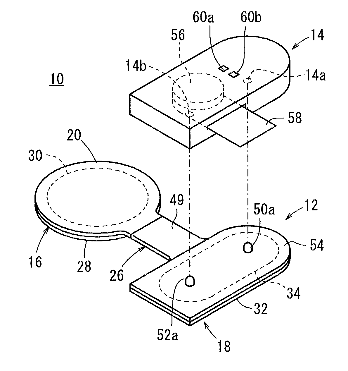
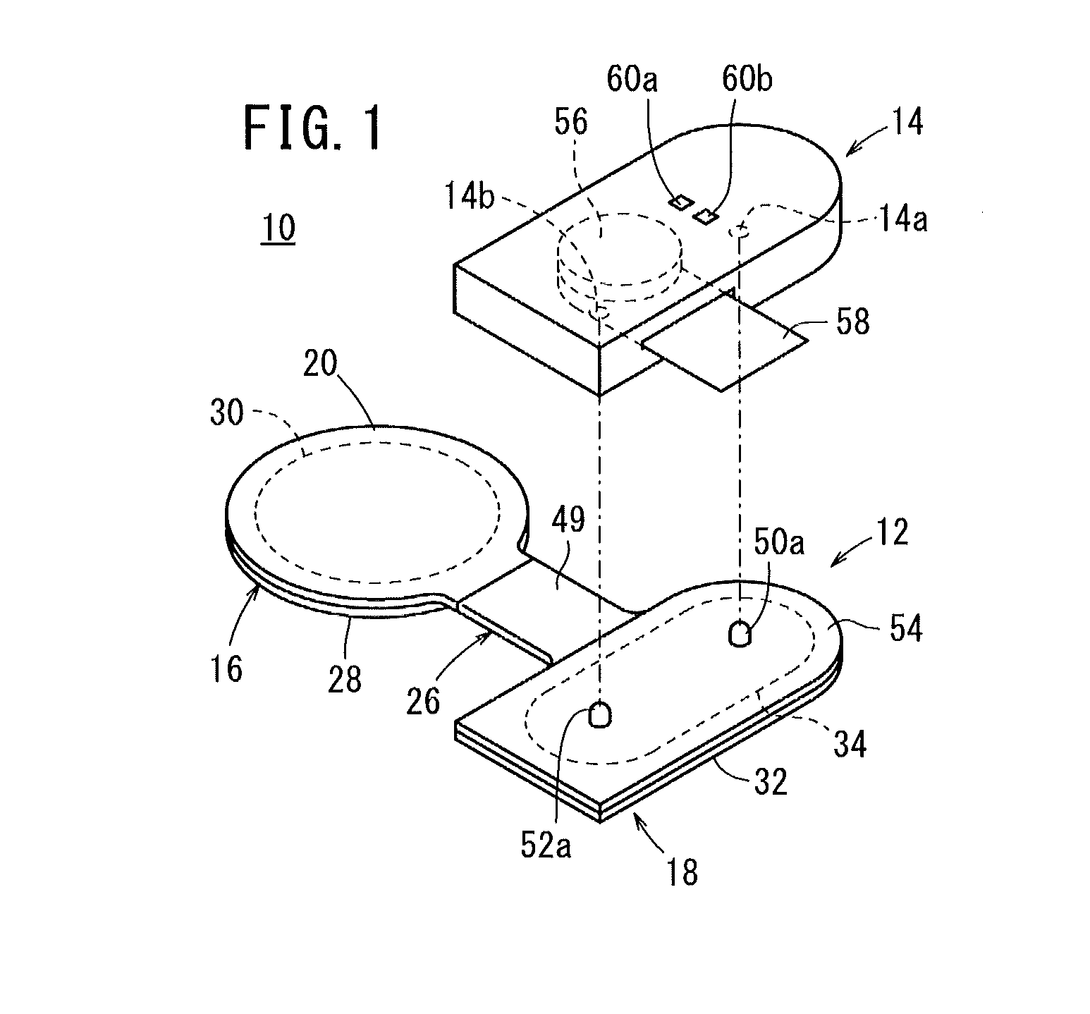
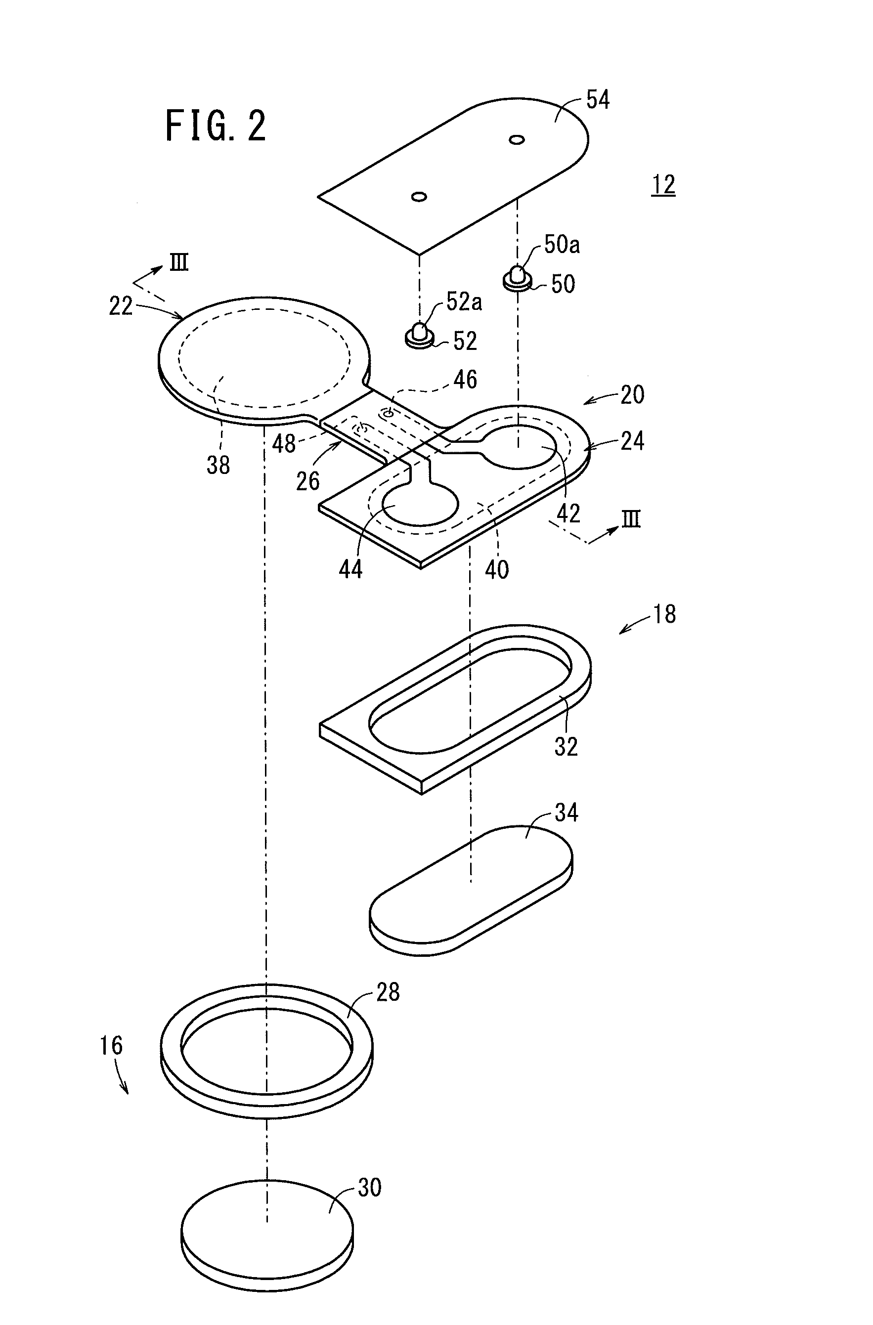
[0016]According to the present invention, a direct current is supplied between the first electrode and the second electrode at a predetermined cycle, and an alternating current is supplied between the first electrode and the second electrode during the first period in which a direct current is not supplied, whereby the capacitance between the first electrode and the second electrode is obtained. Therefore, it is possible to obtain the contact area between the first and second contact members and the external conductor. As a result, it is possible to supply a direct current to the external conductor (the skin, for example) such that the density of the direct current is kept constant. Therefore, even when the contact area decreases, it is possible to continue the energization without causing an adverse effect on the skin of a patient.

Problems solved by technology

However, in the above techniques described in Japanese Laid-Open Patent Publication Nos. 2001-120669 and 2000-237330, when the patch partially comes off the skin, and the contact area between the patch and the skin thereby decreases, although it is possible to stop energization, it is not possible to continue energization while taking into account the decrease of the contact area.
On the other hand, if energization is merely continued when the contact area decreases, the applied current density increases with decreasing contact area, which causes an adverse effect on the skin of a patient.

Method used


Image

  • Transdermal drug administration device
  • Transdermal drug administration device
  • Transdermal drug administration device

Examples


modification 9

[0118](Modification 9)

[0119]In Modifications 5 to 8 described above, the holes 210a and 210b are disposed on the insulating film 212 so as to be symmetric with respect to a straight line that is perpendicular to a straight line connecting the centers of the circular magnetic bodies 206a and 206b and passes through the midpoint M of the straight line connecting the centers. Therefore, if the energization device 204 is attached to the patch 202 in an orientation that is opposite to the predetermined orientation (by rotating the energization device 204 by 180 degrees), that is, if the energization device 204 is attached to the patch 202 such that the permanent magnet 216a attracts the magnetic body 206b, and the permanent magnet 216b attracts the magnetic body 206a, the spring probe 214a makes contact with the conductive plate 208b which is exposed through the hole 210b, and the spring probe 214b makes contact with the conductive plate 208a which is exposed through the hole 210a. There...

modification 10

[0124](Modification 10)

[0125]The pair of magnetic bodies 206a and 206b is used in Modifications 5 to 9 described above. However, as shown in FIG. 15, a pair of permanent magnets (second magnets) 220a and 220b may be used instead of the pair of magnetic bodies 206a and 206b. In this case, the pair of permanent magnets 216a and 216b of the energization device 204 is arranged such that magnetic poles of the permanent magnets 216a and 216b at a side that makes contact with the patch 202 are different from each other. Further, the permanent magnet 220a is provided instead of the magnetic body 206a, and the permanent magnet 220b is provided instead of the magnetic body 206b. When the energization device 204 is attached to the patch 202, the permanent magnets 220a and 220b are required to attract the permanent magnets 216a and 216b, respectively. Therefore, the pair of permanent magnets 220a and 220b is arranged in the patch 202 such that a magnetic pole of the permanent magnet 220a at a s...

modification 11

[0128](Modification 11)

[0129]In Modifications 5 to 10, as shown in FIGS. 10 and 11, the conductive plates 208a and 208b are respectively exposed through the holes 210a and 210b of the insulating film 212. However, the conductive plates 208a and 208b may be disposed over the holes 210a and 210b of the insulating film 212, thereby allowing the conductive plates 208a and 208b to make contact with the spring probes 214a and 214b, respectively.

[0130]Further, in the above embodiment, the insulating film 212 is disposed on the reference-side region 24 as shown in FIGS. 10 and 11. However, the insulating film 212 may not be provided. In this case, the diameter of each of the terminal bases 42a and 44a may be made smaller so as to be equal to the diameter of each of the holes 210a and 210b, and the terminal bases 42a and 44a may be arranged at the same positions as the respective holes 210a and 210b. Further, the insulating film 212 that covers only the connection lines 42b and 44b may be di...


PUM


Abstract

A transdermal drug administration device which comprises a patch that is provided with: a donor gel in which a medical agent is sealed; a reference gel; a first electrode that is connected to the donor gel; and a second electrode that is connected to the reference gel. When the patch is applied to the skin, a direct current is applied between the first electrode and the second electrode at a predetermined cycle and an alternating current is applied between the first electrode and the second electrode during the periods when a direct current is not applied, thereby obtaining the capacitance. The application state of the patch is determined based on the thus-obtained capacitance.

Description

TECHNICAL FIELD[0001]The present invention relates to a transdermal drug administration device using the principle of iontophoresis that allows a medical agent to infiltrate a skin of a human being by passing a low electric current through the skin.BACKGROUND ART[0002]Transdermal drug administration methods include an iontophoresis. The iontophoresis is a method in which positive and negative electrodes are attached to respective two separated points on a skin, and an electric current is passed from one of the electrodes across the stratum corneum to the other electrode to thereby move a charged drug on the basis of the principle of electrophoresis, whereby transdermal drug absorption is facilitated. In this case, the current is basically constant. The area of each of the electrodes is also constant. Therefore, the current density, which is current per unit area, is also constant.[0003]One of the positive and negative electrodes is in contact with a gel containing a drug, and referr...

Claims


Application Information

Patent Timeline
Patent Type & Authority Applications(United States)
IPC IPC(8): A61N1/30
CPCA61N1/303A61N1/044A61N1/325
Inventor YAEGASHI, MITSUTOSHI
Owner TERUMO KK
Why Eureka
Try Eureka