
Ozone and plasma generation using electron beam technology

a technology of electron beam and ozone, which is applied in the direction of energy-based chemical/physical/physical-chemical processes, chemical discharge tubes, electric discharge tubes, etc., can solve the problems of change in reaction efficacy, difficult or impossible to precisely control the electric field, and fundamental limitations of generating the electric field in the same chamber

Inactive Publication Date: 2013-10-31
HITACHI ZOSEN CORP
View PDF8 Cites 7 Cited by
  • Summary
  • Abstract
  • Description
  • Claims
  • Application Information

AI Technical Summary

Benefits of technology

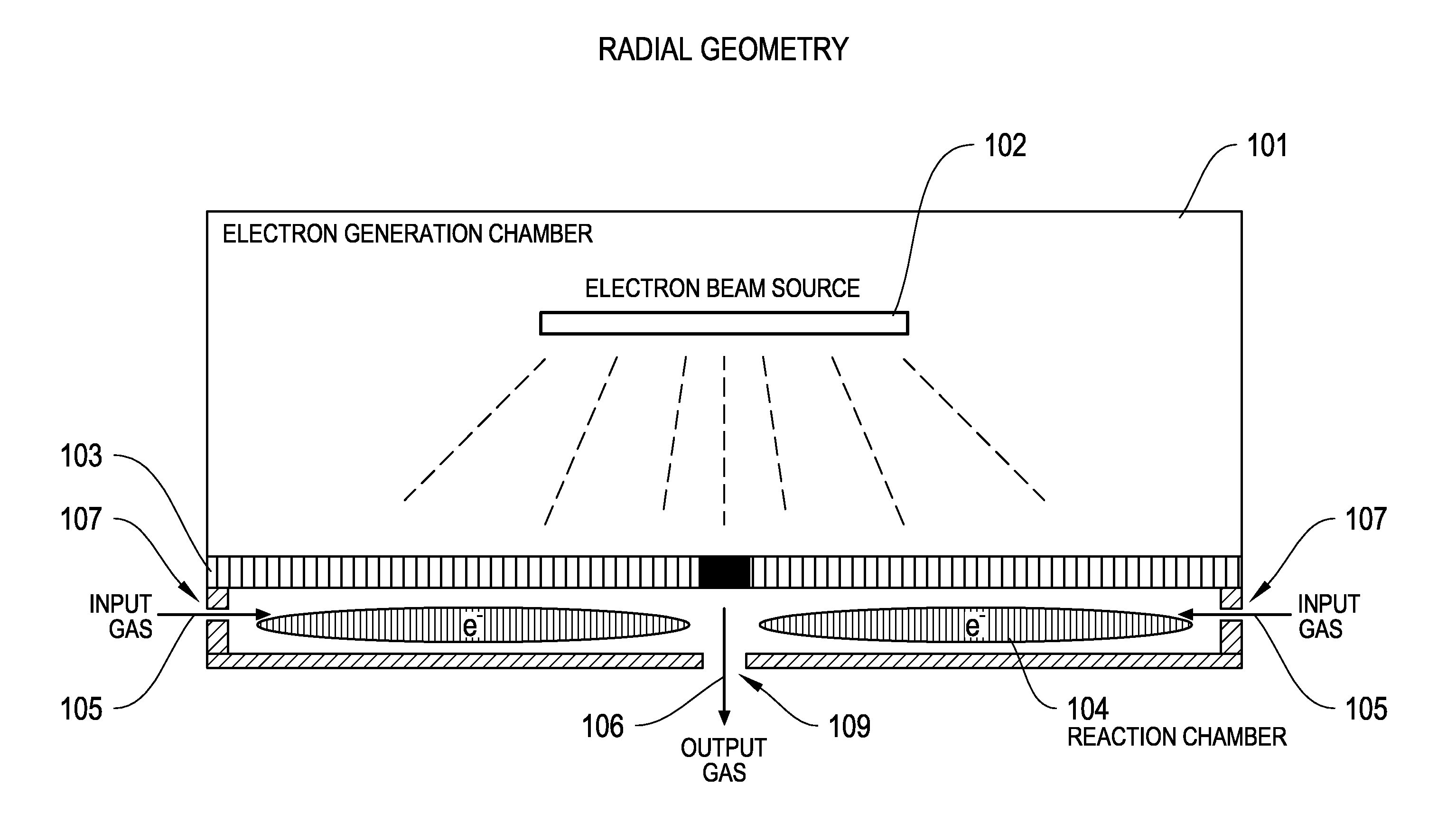
The patent describes systems and methods for generating ozone or plasma using a beam of electrons. Electron generation and reaction chambers are separated by an electron permeable barrier to maintain a vacuum and prevent non-electron material from passing through. The electron beam is generated and accelerated in the electron generation chamber, which is sealed to prevent non-electron material from passing out. The input gas source introduces an input gas into the reaction chamber, where it reacts with the beam of electrons to form plasma or ozone. The output gas passes from the reaction chamber to a wafer processing chamber. The technical effect is a more efficient and precise method for generating plasma or ozone for use in semiconductor device manufacturing.

Problems solved by technology

There are fundamental limitations of generating the electric field in the same chamber as where the input process gas is dissociated into ozone or plasma.
One limitation is that the reacted gas can modify the surface of the chamber in such a way as to alter the way in which the electric field is generated, resulting in a change in reaction efficacy.
A second limitation is that the reacted gas can modify the surface of the chamber in such a way as to create additional unwanted particles.
A third limitation is that it is difficult or impossible to precisely control how the electric field interacts with the process gas, limiting the flexibility of the process.
Known processes for overcoming these limitations for ozone and plasma generation generally result in reduced efficacy, higher process variability, lower efficiency, increased system complexity, higher cost, and increased system maintenance.
One limitation is the detrimental modification of the discharge surface as a result of resultant process gas (i.e. ozone) interaction with those surfaces.
A result of this gradual detrimental modification is the gradual reduction in concentration of the ozone generated due to loss of the effective discharge surface.
Precise gap control and cooling introduce complexity to the overall design of the system and variability in the resultant process gas across different systems.
In addition, precise gap control allows for only limited control over the energy levels of the electrons.
These additional particles are problematic for semiconductor and other industries.
Furthermore, conventional methods result in only partial control over the energy levels of the electrons.

Method used


Image

  • Ozone and plasma generation using electron beam technology
  • Ozone and plasma generation using electron beam technology
  • Ozone and plasma generation using electron beam technology

Examples


Embodiment Construction

[0024]To provide an overall understanding of the systems and methods described herein, certain illustrative embodiments will now be described, including a system for constructing ozone or plasma generators that create an electric field in a separate chamber from the reaction chamber. For illustrative purposes, the systems and methods described herein are discussed with reference to providing gas to a wafer processing system. However, it will be understood by one of ordinary skill in the art that the systems and methods described herein may be adapted and modified as is appropriate for the application being addressed and that the systems and methods described herein may be employed for many suitable applications, and that the systems and methods may have other additions and modifications will not depart from the scope thereof.

[0025]FIG. 1 illustrates one embodiment of a device 100 using radial geometry for generating ozone or plasma. FIG. 1 illustrates the device 100 having an electr...


PUM


Abstract

This invention proposes, among other things, systems and methods for providing ozone generators or plasma generators that generate an electric field in an electron generation chamber that is separate from a reaction chamber. An electron beam emitter in an electron generation chamber is configured to emit a beam of electrons and is separated from the reaction chamber by an electron permeable barrier that provides a window through which the beam of electrons passes. The electrons are accelerated to the required energy in the electron generation chamber and transmitted through the barrier to the reaction chamber, where an input gas source introduces an input gas into the reaction chamber. The input gas may react with the beam of electrons inside the reaction chamber to form an output gas comprising a plasma or a concentration of ozone, and the output gas passes from the reaction chamber to a wafer processing chamber.

Description

REFERENCE TO RELATED APPLICATIONS[0001]This application claims priority under 35 U.S.C. §119 to U.S. Provisional Patent Application 61 / 423,693, entitled “Ozone and Plasma Generation Using Electron Beam Technology,” filed Dec. 16, 2010, which is incorporated herein in its entirety.FIELD OF THE INVENTION[0002]In general, the invention relates to systems and methods for generating ozone and plasma using electron beam technology.BACKGROUND[0003]Ozone and plasma generation technologies rely on the principle of supplying energy to an input gas, resulting in the formation of charge carriers (electrons and ions) as well as additional plasma species. The most commonly used method for generating and sustaining ozone and plasma for industrial applications is by applying an air electric field to the input gas. There are several methods for generating and applying an electric field for these applications. Typically, ozone a id plasma gene ion technologies are configured in such way that the elec...

Claims


Application Information

Patent Timeline
Patent Type & Authority Applications(United States)
IPC IPC(8): B01J19/08
CPCB01J19/085C01B13/10H01J3/02H01J33/00H01J37/3233H01J37/32357H01J37/32816
Inventor BAKHTARI, KAVEH
Owner HITACHI ZOSEN CORP
Learn More