Electrical relay control arrangement for switching an electrical relay at zero crossing of an ac mains supply

Inactive Publication Date: 2013-10-31
HENDON SEMICON
View PDF2 Cites 31 Cited by
  • Summary
  • Abstract
  • Description
  • Claims
  • Application Information

AI Technical Summary

Benefits of technology

[0037]Advantageously there has been no additional components that have to be used

Problems solved by technology

One of the major determinants as to the degree of burn out and damage to the mechanical contact electrodes will be the magnitude of current flowing at that moment of time when the actual mechanical contact electrodes are pulled closed or at the time that they are physically released.
As is to be expected if the mechanical contacts are being physically pulled closed or released at that moment of time when AC mains supply is at its peak AC current is being switched at its maximum potentially leading to a burn out and/or welding shut of the respective mechanical contact electrodes.
Nonetheless this involves connecting add

Method used


Image

  • Electrical relay control arrangement for switching an electrical relay at zero crossing of an ac mains supply

Examples


Embodiment Construction

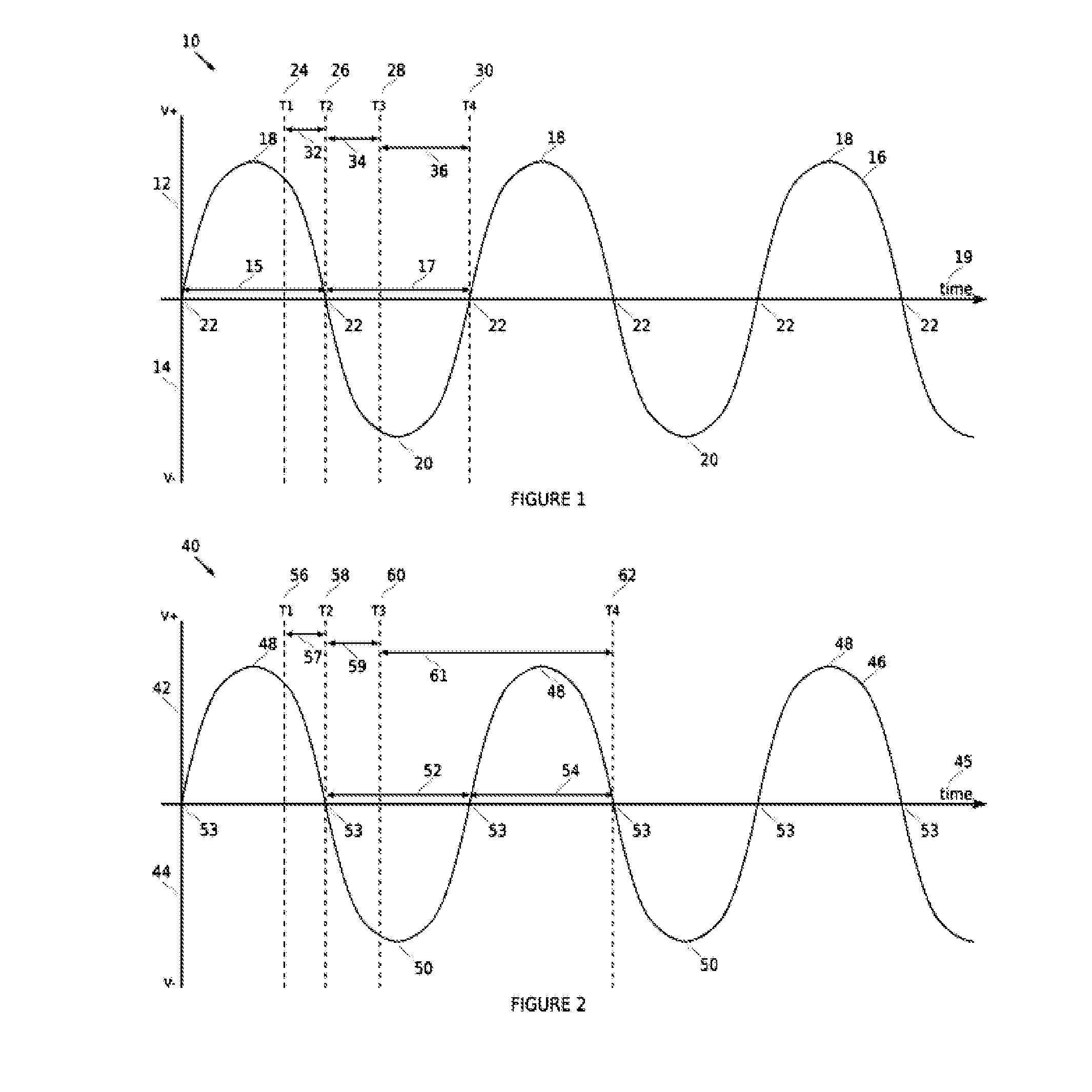
[0043]Referring to FIG. 1 wherein the embodiment shown generally as (10) includes voltage, recognizes a positive voltage (12) and negative voltage (14) with time shown generally as (19).

[0044]The AC mains supply wave form (16) includes a series of positive main peaks shown as (18) along with negative main peaks (20) and the intermittent zero crossing intervals shown generally as (22).

[0045]For an AC mains supply at 50 Hz the zero crossings are 10 ms apart shown generally as (15) and (17).

[0046]T1 (24), T2 (26), T3 (28) and T4 (30) represent various events which ultimately lead to the physical closing or opening of the mechanical contacts in the electrical relay which is under the influence of the control arrangement for this invention at a zero crossing interval.

[0047]T1 represented as (24) is when the micro-processor comes into communication with a switching signal which is communicating to the micro-processor that there is a requirement to switch the electrical relay between an ‘o...


PUM


Abstract

An electrical relay contact arrangement for switching an electrical relay ‘on’ or ‘off’ at zero crossings of an AC mains supply, wherein the arrangement rather than immediately sending a control signal from a microprocessor to the input of the electrical relay to close or open the mechanical electrode contacts when switching is required, relies upon a time interval made up two delays, firstly when the microprocessor first recognizes switching is required there is a waiting period until the next zero crossing, and then a further delay which is the time difference between the lag times of the mechanical contact electrodes physically opening or closing and that of the next zero crossing.

Description

FIELD OF THE INVENTION[0001]This invention relates to an electrical control arrangement of switching an electrical relay on or off and vice versa as required in order to interrupt or connect an electrical supply to a load.[0002]More particularly this invention relates to a unique relay control arrangement and method which is able to accommodate the switching of an electrical relay to an on or off status or vice versa so as to control the AC mains supply to a load wherein such control focuses around the physical electrical contacts of the relay being pulled together or released substantially during zero crossing intervals of the AC mains supply and away from the AC mains supply peaks.BACKGROUND OF THE INVENTION[0003]Electrical relays for the most part are electrically operated switches that are both electrical and mechanical in nature in that the electrical relay converts a magnetic flux generated by the application of a low voltage electrical control signal across the relay terminal...

Claims


Application Information

Patent Timeline
IPC IPC(8): H01H47/18
CPCH01H47/18H01H9/56
Inventor MURFETT, DAVIDFRANCIS, STEPHEN
Owner HENDON SEMICON
Why Eureka
Try Eureka