Resonant converter system having synchronous control circuit and controlling method thereof

a synchronous control circuit and synchronous converter technology, applied in the direction of electric variable regulation, process and machine control, instruments, etc., can solve the problems of large voltage spikes across the corresponding rectifying switch, the complexity of the synchronous rectifying technology of the resonant converter, and the use of the synchronous rectifying technology in the resonant converter, etc., to achieve the effect of low loss

Active Publication Date: 2009-04-16
DELTA ELECTRONICS INC
View PDF11 Cites 69 Cited by
  • Summary
  • Abstract
  • Description
  • Claims
  • Application Information

AI Technical Summary

Benefits of technology

[0009]It is therefore an object of the present invention to provide a resonant converter system having a synchronous rectification control circuit such that a different comparison threshold value is used for each different load current to make s

Problems solved by technology

But there are certain problems regarding using the synchronous rectification technology in the resonant converters.
Viewing from FIG. 2, there are no direct corresponding relationships among VQ5/VQ6, and gate driving signals VQ1, VQ4, VQ2 and VQ3, thus VQ5/VQ6 can not be simply composed by using the primary side driving signals VQ1, VQ4, VQ2 and VQ3, which results in the complexity of the synch

Method used


Image

  • Resonant converter system having synchronous control circuit and controlling method thereof
  • Resonant converter system having synchronous control circuit and controlling method thereof
  • Resonant converter system having synchronous control circuit and controlling method thereof

Examples


Embodiment Construction

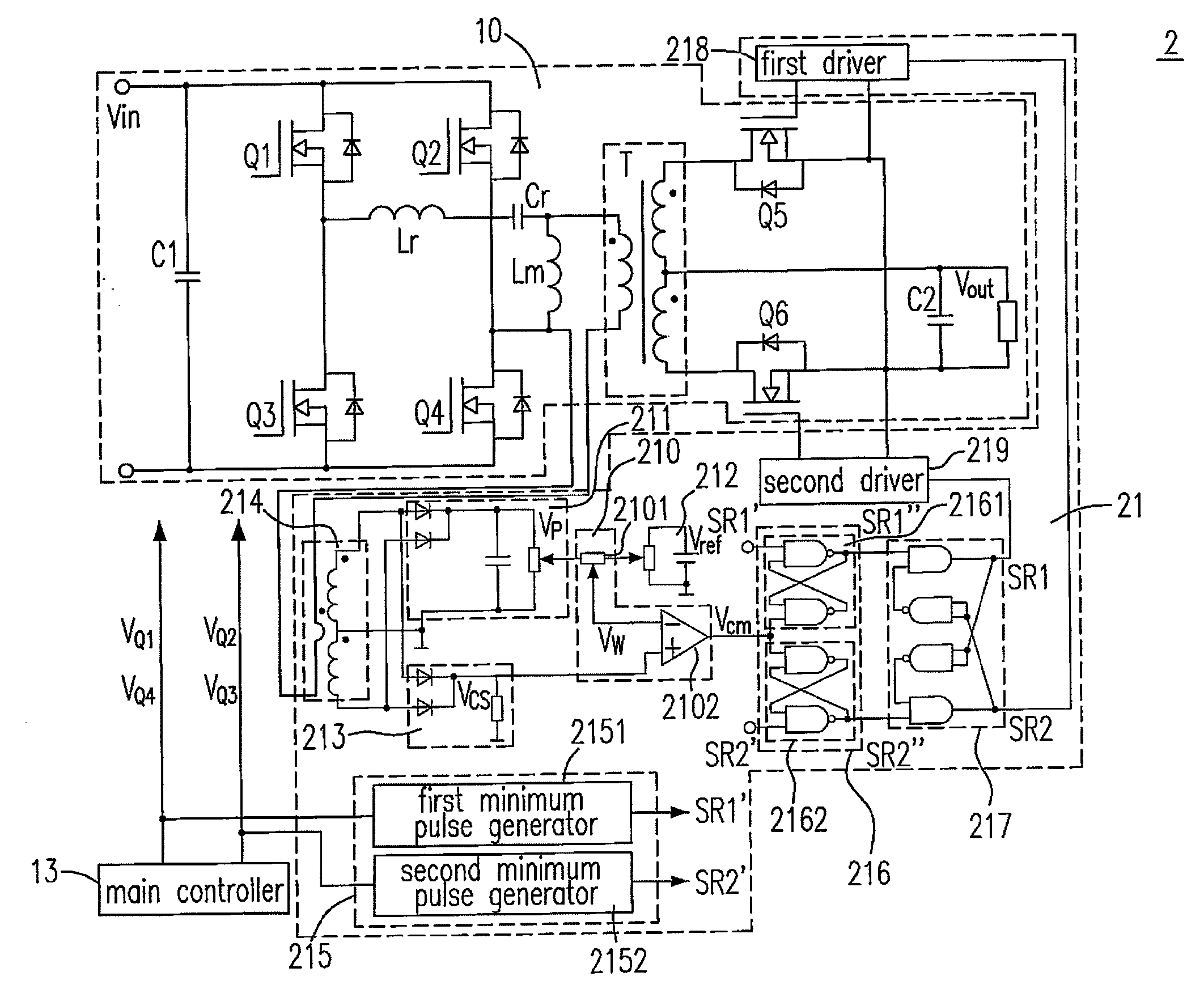
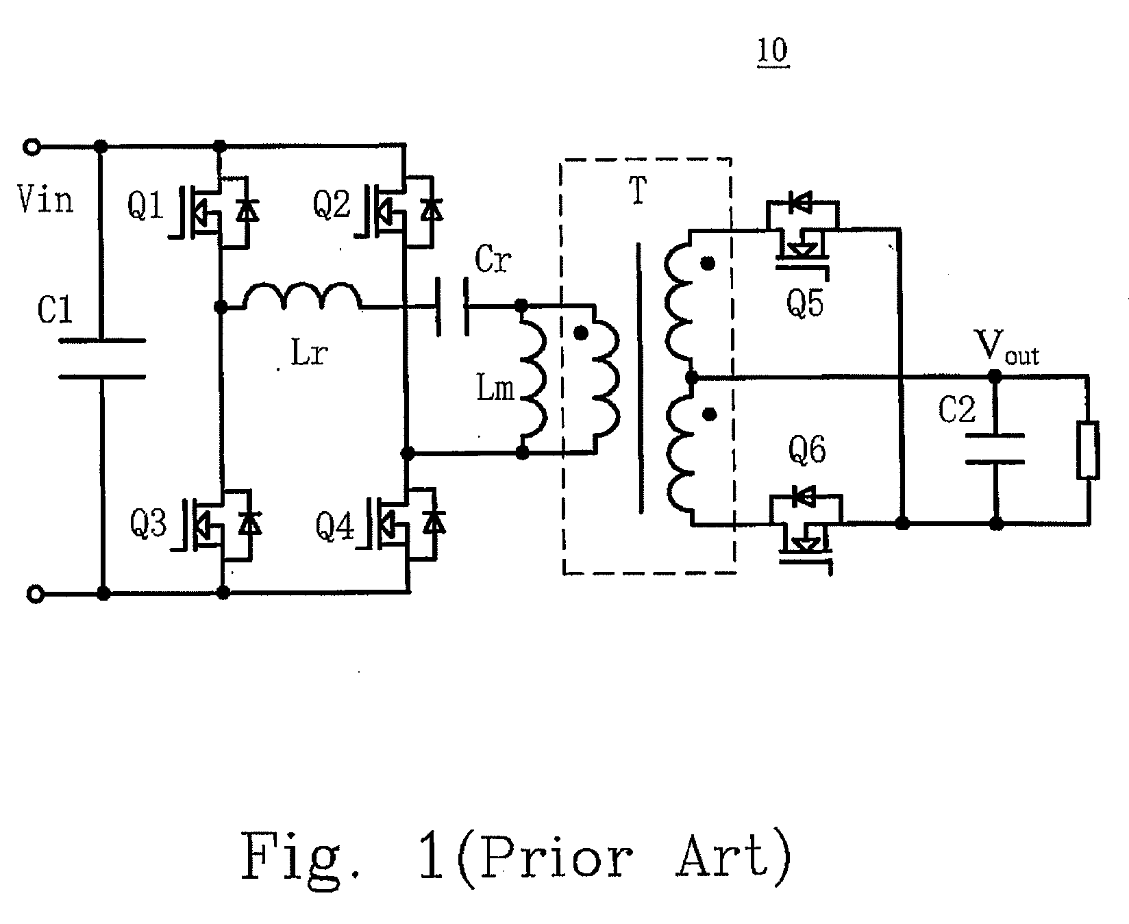
[0043]A DC / DC full-bridge LLC resonant converter among various resonant converters is employed as an example to describe the resonant converter system and the controlling method thereof proposed in the present invention. And the controlling method can be used in other resonant converters e.g. series resonant converter, parallel resonant converter etc.

[0044]Please refer to FIGS. 6(a)-6(c), it shows the basic principle of the present invention, which is that a reflection signal Vp representing the peak value of the turn-on current of a synchronous rectifying switch, a reference voltage Vref and a current sensed signal Vcs which represents the turn-on current of the synchronous rectifying switch are weighted and compared with each other to get a weighted turn-off signal Vcm of the synchronous rectifying switch. In FIG. 6(a), it is a schematic circuit diagram of a signal generation apparatus 210 according to the first preferred embodiment of the present invention. The signal generation ...


PUM


Abstract

The configurations of a resonant converter system and a controlling method thereof are provided. The proposed resonant converter system includes a resonant converter receiving an input voltage for outputting an output voltage, a rectifying device having a first rectifying switch and a synchronous rectification control circuit coupled to the resonant converter and including a signal generation apparatus generating a weighted turn-off signal to turn off the first rectifying switch at a zero crossing point of a first current flowing through the first rectifying switch.

Description

FIELD OF THE INVENTION[0001]The present invention relates to a resonant converter system. More particularly, the present invention relates to a resonant converter system having a synchronous rectification control circuit.BACKGROUND OF THE INVENTION[0002]Due to that the power density of the power supply and the efficiency of the circuit are continuously increased, the resonant converters are becoming more and more valued for their relatively higher efficiencies and the synchronous rectification technology are commonly applied due to its relatively lower turn-on loss.[0003]But there are certain problems regarding using the synchronous rectification technology in the resonant converters. These problems are addressed by using FIGS. 1 to 5 as examples. As shown in FIG. 1, it is a circuit diagram of a DC / DC full-bridge LLC resonant converter 10 in the prior art. In which, it receives an input voltage Vin for generating an output voltage Vout, and includes an input capacitor C1, a full-bri...

Claims


Application Information

Patent Timeline
IPC IPC(8): H02M3/335
CPCH02M3/33592Y02B70/1475Y02B70/1433H02M3/3378Y02B70/10Y02P80/10
Inventor WU, HONGYANGWANG, BINZENG, JIANHONGYING, JIANPINGXIN, XIAONI
Owner DELTA ELECTRONICS INC
Why Eureka
Try Eureka