
Eureka
For R&D, Eureka makes reading and utilizing patents & technical documents easy.
Eureka AIR
Designed for self-driven R&D workflows. Generate viable solutions, solve complex R&D challenges, empower your innovation with AI.

Eureka Materials
Designed for material experts only. Revolutionize your material R&D, from search, analyze, to developing new materials.

TechResearch
Generate reliable direction feasibility study reports for your R&D in just a few steps.

TechSeek
Discover and master advanced knowledge NOW. Basics, ideas, possibilities, all at once.

TechMind
As an expert in R&D Theories, TechMind can generates customized viable solutions instantly.

TechRisk
Analyze your overall solution with one click, know your potential R&D risks in advance.

TechMonitor
Get weekly tech updates, stay abreast of the latest tech innovations and key insights.
Oct probe
- Summary
- Abstract
- Description
- Claims
- Application Information
AI Technical Summary
Benefits of technology
Problems solved by technology
Method used
Image

Examples
example 1
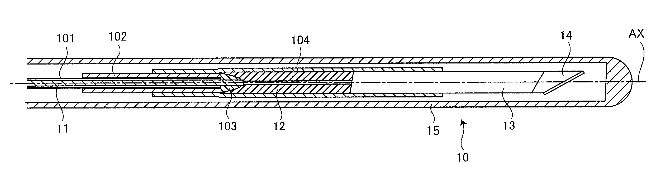
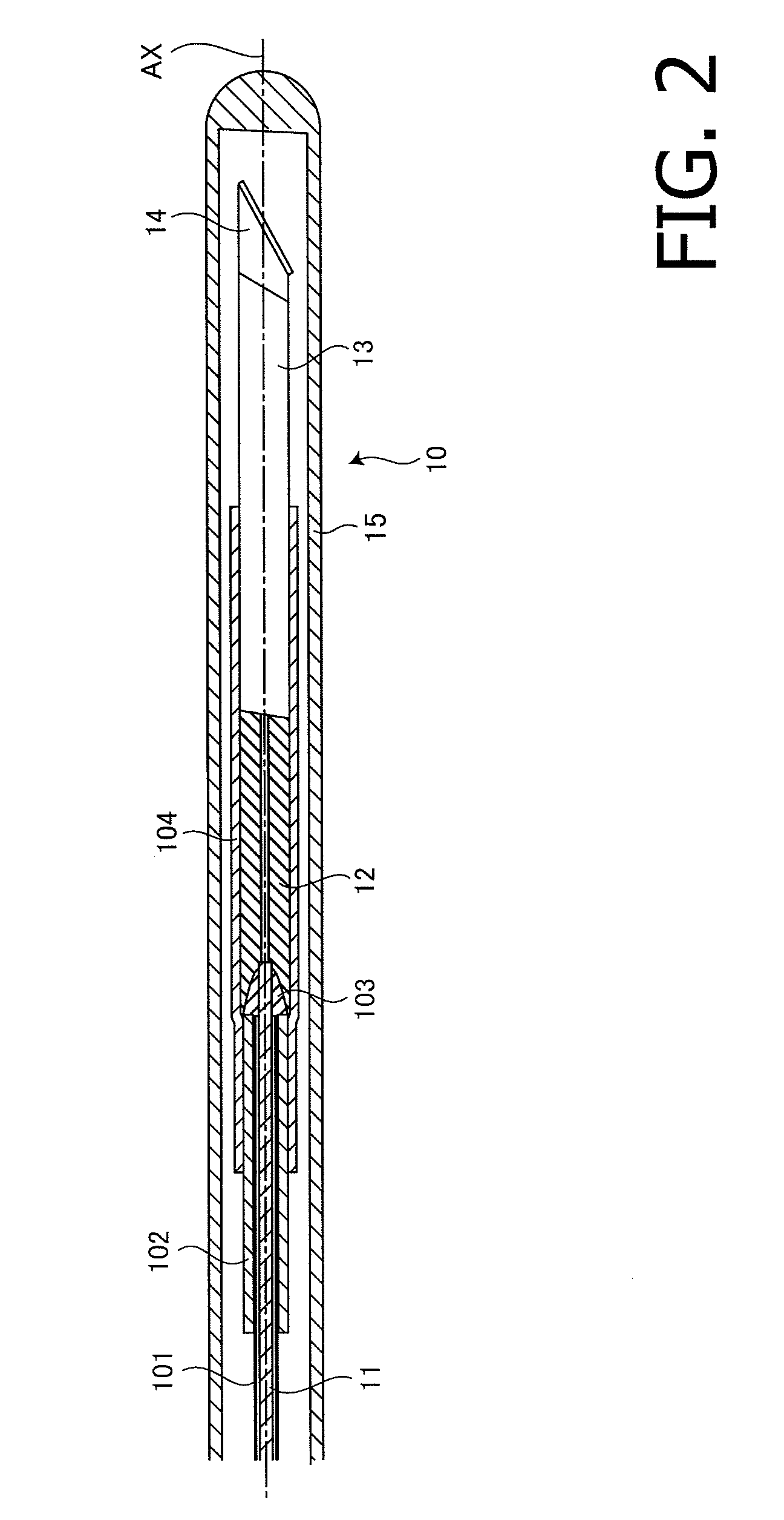
[0031]FIG. 2 illustrates an internal configuration of the OCT probe 10 according to the example 1 of the invention. To an outer circumferential surface of a PTFE (Polytetrafluoroethylene) inner sheath 101 covering a portion near the tip of the optical fiber 11 according to the example 1, an FEP (Fluorinated Ethylene Propylene) heat shrinkable tube 102 is pressurized and joined. After pressure joining of the FEP heat shrinkable tube 102, the tip surface of the optical fiber 11 is adhered to the proximal surface of the ferrule 12 with a thermosetting adhesive 103. To the outer circumferential surface extending from a portion near the tip of the heat shrinkable tube 102 to a portion near the proximal end of the GRIN lens 13 via the ferrule 12, an FEP heat shrinkable tube 102 is pressurized and joined, so that the adhered point is strengthened.
[0032]The inventors of the invention understand that a primary factor that obstructs smooth transmission of the rotation torque produced on the p...
example 2
[0033]FIG. 3 illustrates an inner configuration of the OCT probe 10 according to the example 2 of the invention. In each example explained below, to elements which are the same as or similar to those of the example 1, the same reference numbers are assigned, and explanations thereof will be simplified or omitted.
[0034]Since a coating surface of the fluorocarbon resin, such as PTFE exemplified in the example 1, has a low frictional coefficient, almost no frictional resistance is caused. In the example 2, in place of PTFE, the whole outer circumferential surface expending from the tip to the proximal end of the optical fiber 11 is covered with a PI coat 111 as primary coating, and is further covered with a PFA coat 112 as secondary coating. In the example 2, since no clearance is secured between the optical fiber 11 and a coating layer, the rotation torque of the radial scan motor 32 is transmitted more smoothly and effectively to the tip side of the optical fiber 11. In the example 2...
example 3
[0035]The inventors of the invention understand that a primary factor that causes the swinging motion of the tip portion of the optical fiber 11 in the outer sheath 15 is a shift between the barycenter of the component fixed to the tip of the optical fiber 11 and the rotation center axis (the reference axis AX) of the optical fiber 11. In the example 2, of the components accommodated in the outer sheath 15, components other than the GRIN lens 13 and the deflection prism 14 are arranged such that barycenters thereof coincide with the rotation center axis (reference axis AX) of the optical fiber 11. In other words, the barycenters of the GRIN lens 13 and the deflection prism 14 shift from the reference axis AX. For this reason, in the example 3, a barycenter adjustment member 121 is added to the configuration shown in the example 2.
[0036]FIG. 4 is illustrates an inner configuration of the OCT probe 10 according to the example 3 of the invention. As shown in FIG. 4, the OCT probe 10 ac...
PUM
 Abstract
Description
Claims
Application Information
 - R&D Engineer
- R&D Manager
- IP Professional
- Industry Leading Data Capabilities
- Powerful AI technology
- Patent DNA Extraction
Browse by: Latest US Patents, China's latest patents, Technical Efficacy Thesaurus, Application Domain, Technology Topic, Popular Technical Reports.
© 2024 PatSnap. All rights reserved.Legal|Privacy policy|Modern Slavery Act Transparency Statement|Sitemap|About US| Contact US: help@patsnap.com