Apparatus and method for non contact sensing of forces and motion on rotating shaft

a technology of non-contact sensing and rotating shafts, applied in the field of sensor systems, can solve problems such as inability to meet the needs of maintenance,

Inactive Publication Date: 2013-11-07
PUREKAR ASHISH S +2
View PDF6 Cites 27 Cited by
  • Summary
  • Abstract
  • Description
  • Claims
  • Application Information

AI Technical Summary

Benefits of technology

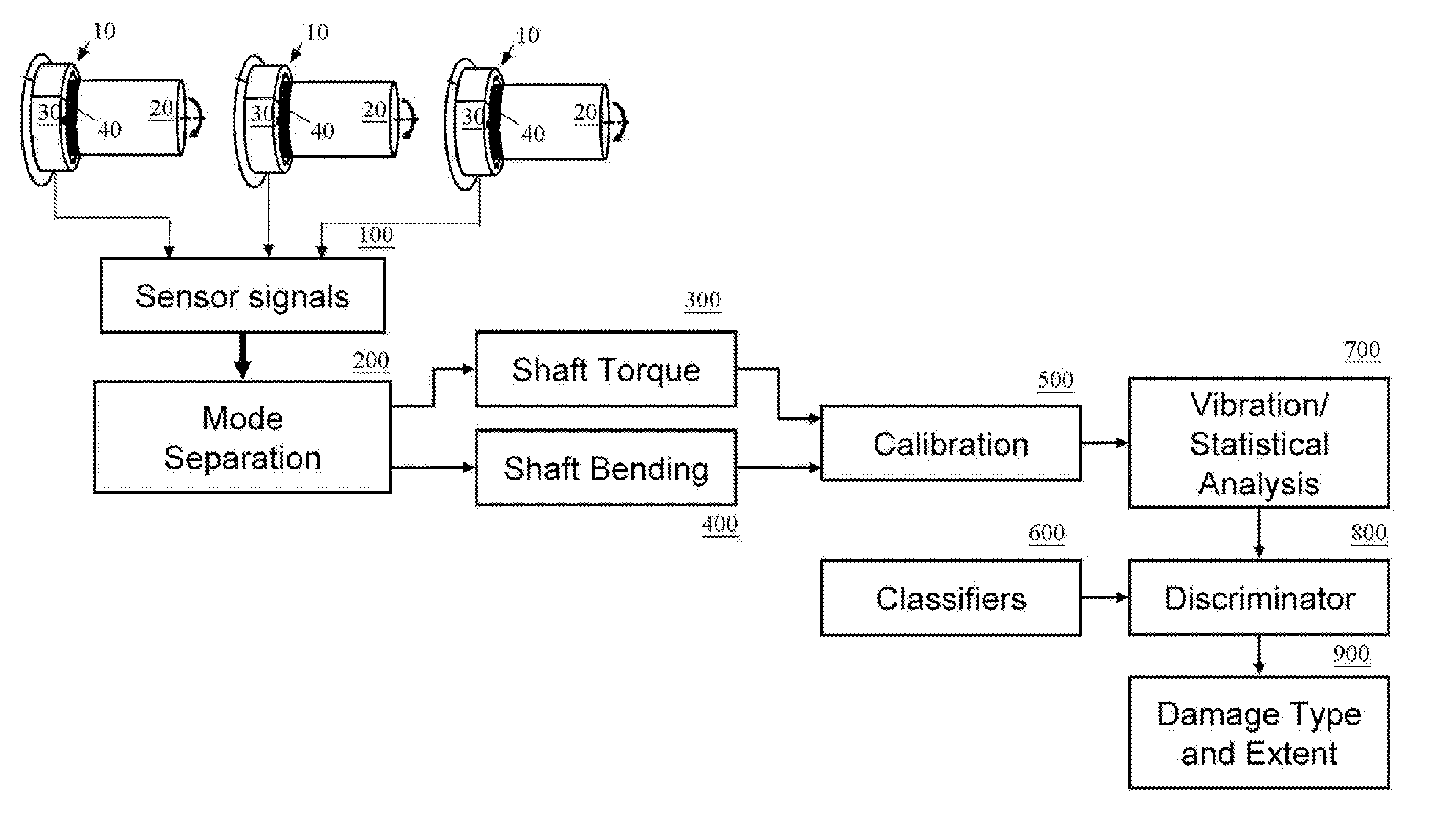
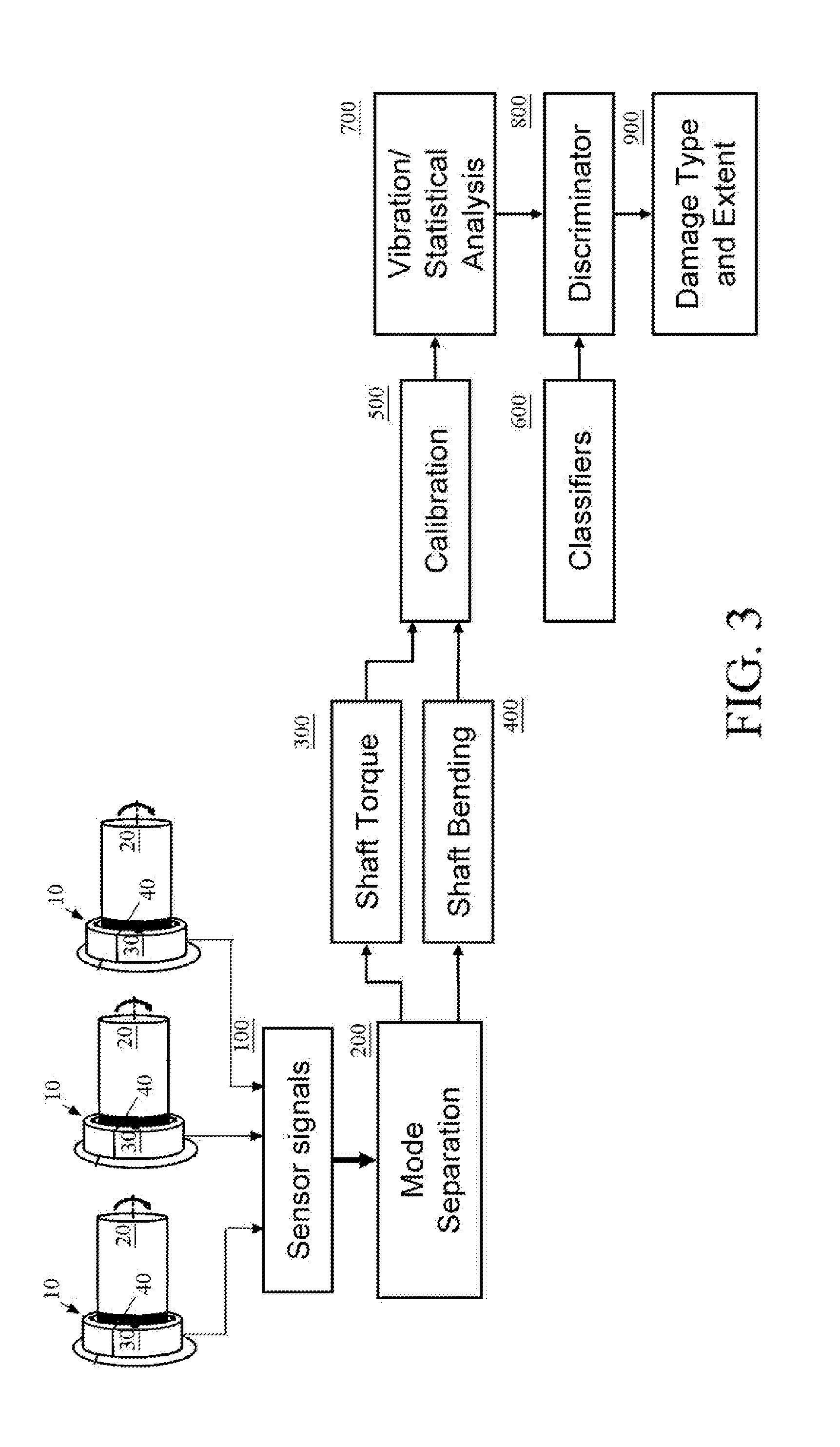
[0011]It is another object to provide a sensor system incorporating the above with the ability to measure any one or more of the following parameters of the shaft: (1) torque, (2) rate of change of torque, (3) shaft speed, (4) shaft position, (5) transverse bending moments in the shaft in 2 directions, (6) axial load, (7) shaft power and / or system efficiency (from combinations of the foregoing measurements).

Problems solved by technology

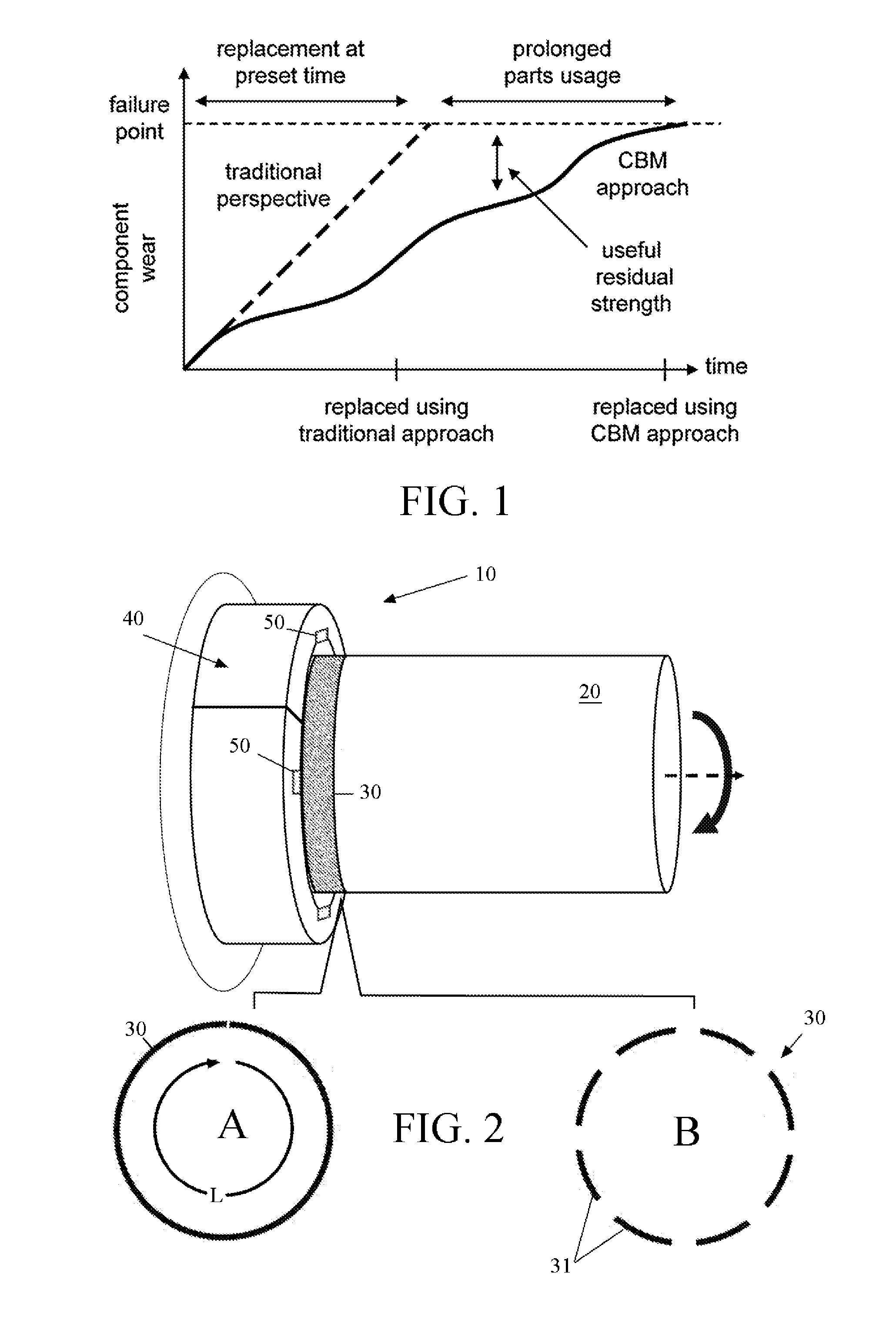
Actual use of the machinery component which does not fall into the assumed usage levels would result in scheduling of maintenance before it is required or after the part has unacceptable levels of damage.
Parts which do not need to be replaced are changed out for newer parts unnecessarily and / or critically damaged parts may stay in service until the next inspection.
Both represent significant inefficiencies in conventional maintenance practices.
These inefficiencies result in unnecessary maintenance actions which increases the total operating cost.
Common damage types include shaft degradation, shaft coupling misalignment, and bearing wear and failure.
For example, if a critically damaged part passes an inspection and fails in the field the vessel will need to be docked for an unwanted teardown to inspect hidden parts.
This approach poses challenges in the CBM context for at least two reasons: 1) brushed slip rings have defined life spans; and 2) retrofit applications are limited as slip rings need to fit over the shaft causing disassembly of the machine.

Method used


Image

  • Apparatus and method for non contact sensing of forces and motion on rotating shaft
  • Apparatus and method for non contact sensing of forces and motion on rotating shaft
  • Apparatus and method for non contact sensing of forces and motion on rotating shaft

Examples


experimental examples

a. Example I

[0033]Magnetostriction is a change in length undergone by ferromagnetic materials under a magnetic field. Iron elongates along the direction of magnetization and is said to have positive magnetostriction. Some materials however may contract along this direction and are said to have negative magnetostriction. The concept of magnetic dipoles is that within the material there are very small north and south magnetic poles. Magnetic domains are small regions of a material that have all of their magnetic dipoles aligned in parallel. In ferromagnetic materials, without the presence of a magnetic field or stress (demagnetized state) the domains within the material have random directions. The total magnetization outside the presence of a magnetic field therefore averages to zero. When a magnetic field is applied, the ferromagnetic crystals tend to align in a preferred crystallographic direction. These are known as the easy directions since if the magnetic field is applied in this...

example 2

b. Example 2

[0036]Galfenol has also been characterized as a strain sensor in bending mode. To illustrate this, FIG. 5(A) shows an experimental setup implemented with a cantilevered aluminum beam (355.6×26.1×3.2 mm3) placed in between two aluminum spacers near its root and bolted onto a load cell. The other end of the load cell is attached to a magnetic shaker. Single crystal Galfenol (Fe84Ga16) patches of dimensions 25.4 mm by 8.5 mm and of two different thicknesses (1.88 mm and 0.38 mm) were used. The patches had the crystallographic directions oriented along their length, width and thickness. The Galfenol patch was bonded onto the beam near its root as shown in FIG. 5(A), so that it experiences the maximum bending moment when the beam is loaded at the tip. A strain gage bonded on the beam surface next to the Galfenol patch measured the strain while a Hall-effect sensor placed at one end of the patch surface was used to obtain a signal proportional to the change in magnetic induct...

example 3

[0037]By acting as a strain sensor, Galfenol can also act as a torque sensor under static conditions. An experimental setup was constructed with a cantilevered polyvinyl chloride shaft (762 mm long and 63.5 mm diameter) bolted at one end to provide a clamped boundary condition. A single crystal Galfenol (Fe84Ga16) patch of dimensions 25.4 mm×8.5 mm×1.88 mm was bonded on the shaft surface near its root as shown in a with orientation shown relative to the compressive and tensile stresses. A Hall-effect sensor placed at one end of the patch surface was used to obtain a signal proportional to the change in magnetic induction in the patch. A permanent magnet placed on the Galfenol patch was used to provide a magnetic bias to the patch to improve its sensing performance. The static torque was applied by hanging dead weights from a load arm attached to the free end of the polyvinyl chloride shaft. The result indicates that the Galfenol patch worked as a linear torque sensor. The torque sen...


PUM


Abstract

A sensor system for analysis of forces and motions on a rotating shaft using non-contact magneto-elastic sensors with the ability to measure any one or more of the following parameters of the shaft: (1) torque, (2) rate of change of torque, (3) shaft speed, (4) shaft position, (5) bending moments in the shaft in 2 directions, (6) axial force, (7) shaft power and/or system efficiency. The sensor system generally includes a magneto-elastic sensor patches fixedly applied to the rotating shaft, and a magnetic field pick up surrounding both said shaft and said magneto-elastic material but not in contact therewith, said magnetic field pick up comprising a clam-shell toroidal collar incorporating a combination of a magnetic field sensors.

Description

CROSS-REFERENCE TO RELATED APPLICATION(S)[0001]The present application derives priority from U.S. Provisional Patent Application No. 61 / 619,141 filed 2 Apr. 2012.BACKGROUND OF THE INVENTION[0002]1. Field of the Invention[0003]The present invention relates to sensor systems and, more particularly, to a system for monitoring loads on rotating components such as shafts in pumps, compressors, motors, turbines, rotor systems, and drive trains which rely on rotating shafts to transmit power. Applications of this sensor system include Condition Based Maintenance, online performance monitoring, and loads measurement.[0004]2. Description of the Background[0005]Condition Based Maintenance (CBM) systems are being actively pursued for a variety of applications for machinery. The goal of a CBM system is to replace parts on an as-needed basis, which differs from conventional maintenance activities in which parts are replaced on a fixed schedule based on estimates from profile loads during design ...

Claims


Application Information

Patent Timeline
Patent Type & Authority Applications(United States)
IPC IPC(8): G01L3/10
CPCG01L3/101G01L3/102G01L3/103G01L1/125
Inventor PUREKAR, ASHISH S.YOO, JIN-HYEONGFLATAU, ALISON BEHRE
Owner PUREKAR ASHISH S
Why Eureka
Try Eureka