2d/3d real-time imager and corresponding imaging methods

a real-time imager and imager technology, applied in the field of real-time imagers, can solve the problems of limiting the capability of moving targets, limiting the achievable frame rate, and significant speed limits of 3d sensors, and achieve the effect of improving the speed, distance and resolution capabilities

a real-time imager and imager technology, applied in the field of real-time imagers, can solve the problems of limiting the capability of moving targets, limiting the achievable frame rate, and significant speed limits of 3d sensors, and achieve the effect of improving the speed, distance and resolution capabilities

US20130293681A1Active Publication Date: 2013-11-07FASTREE3D

Image

  • 2d/3d real-time imager and corresponding imaging methods
  • 2d/3d real-time imager and corresponding imaging methods
  • 2d/3d real-time imager and corresponding imaging methods

Examples


Embodiment Construction

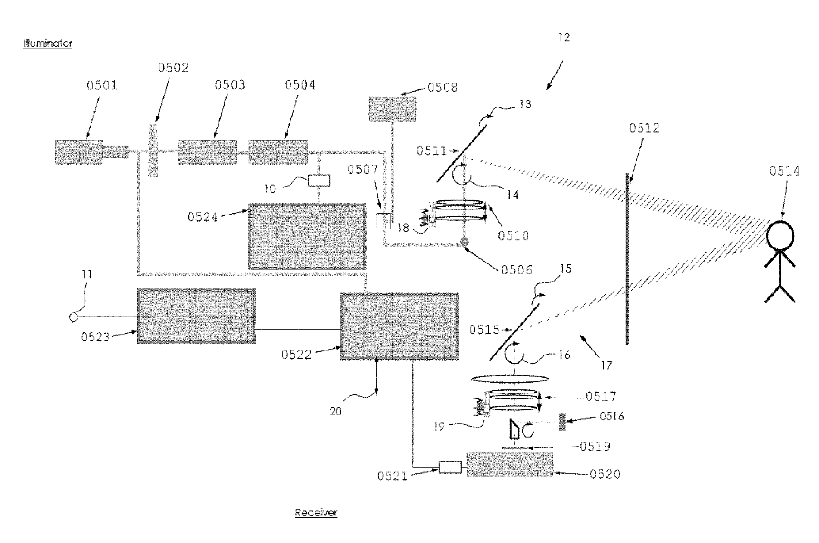
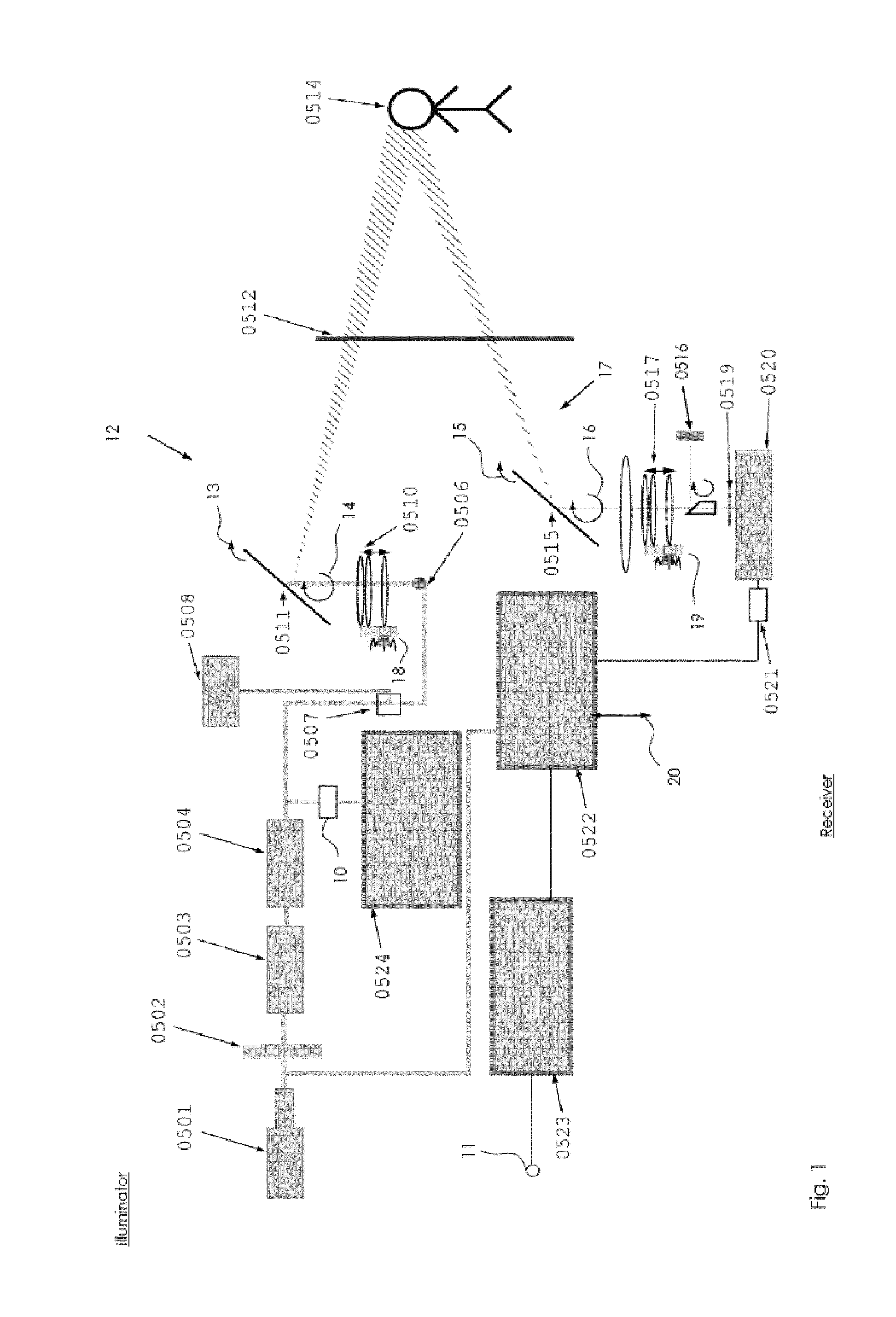
[0039]As it is represented in FIG. 1, the real-time imager of the present invention comprises at least one illuminator and at least one receiver. The optical detector part is represented here at 0520. It is part of the receiver. A main function of the receiver is to convert the output of the detector into an electronic image signal which can be displayed on a screen, and / or stored or transmitted to a computer which uses the imaged scene. Some front-end image processing will also be done as part of the receiver.

The illuminator

[0040]The illuminator produces an illumination pattern on the scene. That pattern is generated with a series of ultra-short laser pulses from at least one source. The means for generating ultra-short laser pulses comprise:[0041]preferably a mode-locked laser source which continuously generates low-jitter pulses with a controlled low optical average power;[0042]a modulator which forms programmed sequences of the generated pulses by removing some of the pulses;[00...


PUM


Abstract

The present invention relates generally to methods and devices of generating an electrical representation of at least one object in a scene in the real word. The detail real-time imager for the representation of a scene of a real world comprises:—at least an illuminator (0501-0511) of said scene providing at least a series of ultra-short power laser pulses with time-related positions; and—a receiver (0515-0523) of a SPAD Single Photon Avalanche Diode detector array according to the method of the invention and associated to at least said series of ultra-short power laser pulses of said illuminator.

Description

TECHNICAL FIELD[0001]The present invention relates generally to a real-time imager containing an illuminating device. That device illuminates a scene with ultra-short laser pulses which are temporally arranged in the form of predetermined illumination patterns. It relates also to imaging methods for acquiring scenes in a large range of directions.BACKGROUND OF THE INVENTION[0002]Existing 2D / 3D imagers use natural light, flash light, artificial lighting, infrared illuminators, or pulsed laser illuminators emitting comparatively long (nanosecond) pulses. Those illuminators send light to the expected targets. A tiny fraction of this light is reflected towards the sensor part of the imager. 2D imagers do not suffer from intrinsic speed limitations, but only sensitivity limits. 3D sensors have significant speed limits due to the round-trip time of the emitted light between the imager and the target. This is aggravated by the significant settling time (dead time) required by most 3D senso...

Claims


Application Information

Patent Timeline
07 Nov 2013
Publication
US20130293681A1
IPC
H04N13/02; G01S17/89
CPC
H04N13/0203; G01S7/483; G01S17/89; H04N13/204
Inventors
BOROWSKI, ANDRE