Valve assembly with isolation valve vessel

a valve assembly and valve valve technology, applied in the field of nuclear power reactor arts, can solve problems such as leakage in the valve room

Active Publication Date: 2013-11-07
NOVA TECH INC +1
View PDF2 Cites 15 Cited by
  • Summary
  • Abstract
  • Description
  • Claims
  • Application Information

AI Technical Summary

Benefits of technology

[0010]The isolation valve assembly can further include a forging including the mounting flange and a second flange to which the isolation valve vessel is secured, the forging having a passageway extending between the mounting flange and the second flange through which the fluid flow line passes. The valve can be a check valve allowing flow out of the mounting flange and blocking flow into the mounting flange. The valve can include first and second valves disposed in the isolation valve vessel inside the sealed volume and arranged in series along the fluid flow line. The isolation valve assembly can further include an external isolation valve disposed outside the isolation valve vessel and outside the sealed volume and operatively connected with the fluid flow line. The valve can include an actuator for moving the valve between open and closed positions. The actuator can be an electric, hydraulic, pneumatic or manual actuator.
[0011]The apparatus can further comprise a nuclear reactor comprising (i) a pressure vessel including a mating flange and (ii) a nuclear reactor core comprising fissile material disposed in the pressure vessel, wherein the mounting flange of the isolation valve is connected with the mating flange of the pressure vessel of the nuclear reactor. The fluid flow line can be a makeup line of a reactor coolant inventory and purification system (RCIPS) and the valve can be a check valve preventing backflow of reactor coolant from the pressure vessel into the makeup line. The fluid flow line can be a coolant letdown line of a reactor coolant inventory and purification system (RCIPS) and the valve can be an actuated valve.
[0012]In accordance with still another aspect, a nuclear reactor comprises a nuclear reactor core comprising a fissile material, a pressure vessel containing the nuclear reactor core immersed in primary coolant disposed in the pressure vessel, and an isolation valve assembly including a valve cover having a single open end with a flange, a spool piece including a first flange and a second flange secured with the flange of the valve cover to define a sealed volume enclosed by the valve cover, a fluid flow line passing through the spool piece and flowing fluid into or out of the first flange, and a valve supported in the sealed volume and operatively connected with the fluid flow line.

Problems solved by technology

Type 3 LOCAs result from leaks that occur in the valve rooms.

Method used


Image

  • Valve assembly with isolation valve vessel
  • Valve assembly with isolation valve vessel
  • Valve assembly with isolation valve vessel

Examples


Embodiment Construction

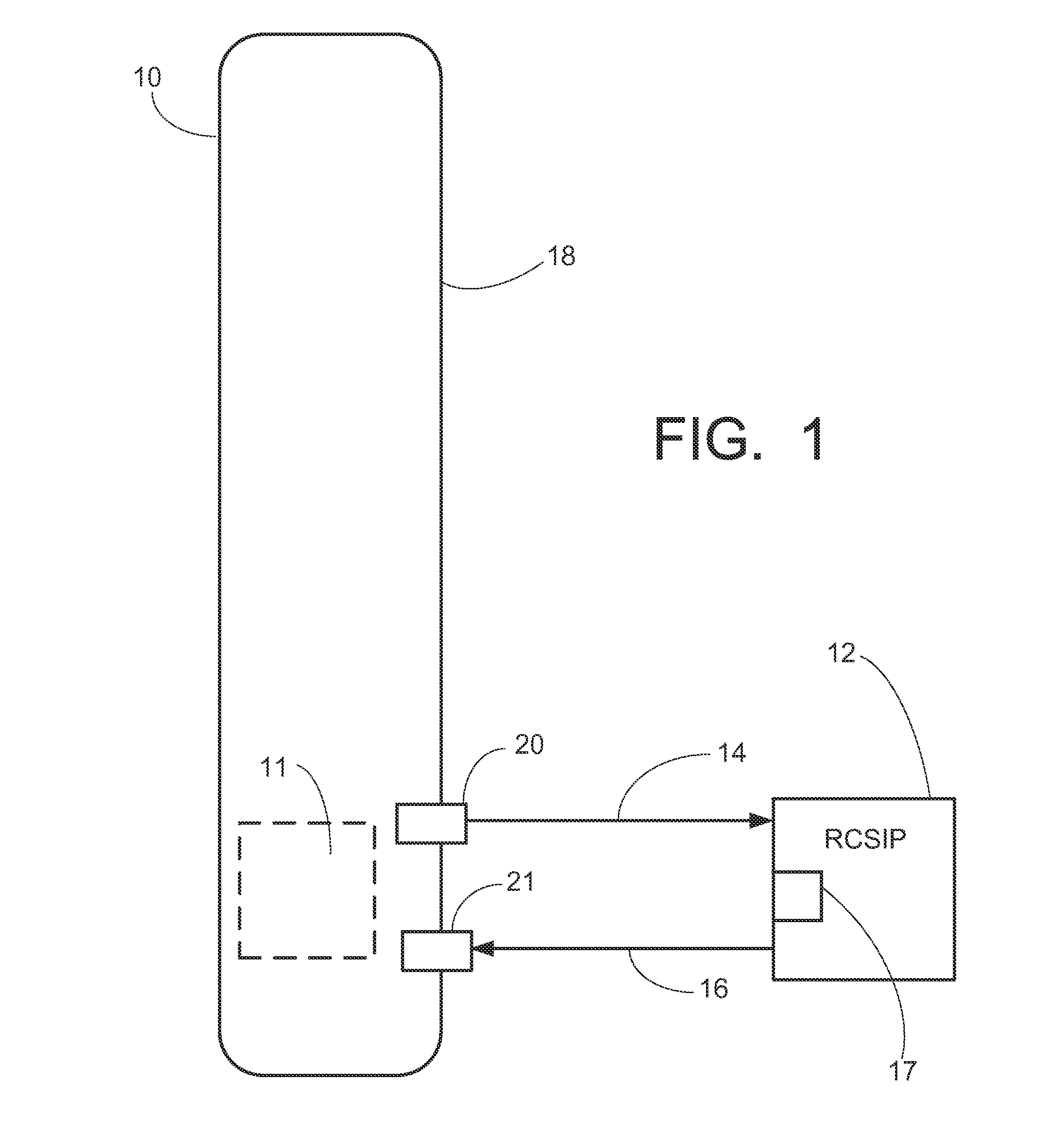
[0020]FIG. 1 is a schematic illustration of a nuclear reactor including a pressure vessel 10. The pressure vessel 10 contains a nuclear reactor core 11 (shown in phantom) disposed at or near the bottom of the pressure vessel 10 and immersed in primary coolant water also disposed in the pressure vessel 10. The pressure vessel 10 further contains numerous internal components that are not shown in FIG. 1 but which are known in the art, such as structures defining a primary coolant flow circuit, e.g. a hollow cylindrical central riser defining a hot leg inside the riser and a cold leg in a downcomer annulus (e.g., flow region) defined between the central riser and the pressure vessel 10, and neutron-absorbing control rods and associated drive mechanisms for controlling reactivity of the nuclear reactor core. Some embodiments, e.g. integral pressurized water reactor (PWR) designs, also include one or more steam generators disposed inside the pressure vessel, typically in the downcomer an...


PUM


Abstract

Apparatuses for reducing or eliminating Type 1 LOCAs in a nuclear reactor vessel. A nuclear reactor including a nuclear reactor core comprising a fissile material, a pressure vessel containing the nuclear reactor core immersed in primary coolant disposed in the pressure vessel, and an isolation valve assembly including, an isolation valve vessel having a single open end with a flange, a spool piece having a first flange secured to a wall of the pressure vessel and a second flange secured to the flange of the isolation valve vessel, a fluid flow line passing through the spool piece to conduct fluid flow into or out of the first flange wherein a portion of the fluid flow line is disposed in the isolation valve vessel, and at least one valve disposed in the isolation valve vessel and operatively connected with the fluid flow line.

Description

[0001]This application claims the benefit of U.S. Provisional Application No. 61 / 625,326 filed Apr. 17, 2012. U.S. Provisional Application No. 61 / 625,326 filed Apr. 17, 2012 is hereby incorporated by reference in its entirety.BACKGROUND[0002]The following relates to the nuclear power reactor arts, nuclear reaction coolant system arts, nuclear power safety arts, and related arts.[0003]Light water nuclear reactors are known for maritime and land based power generation applications and for other applications. In such reactors, a nuclear reactor core comprising a fissile material (for example, 235U) is disposed in a pressure vessel and immersed in primary coolant water. The radioactive core heats the primary coolant in the pressure vessel, and the pressure vessel (or an external pressurizer connected with the pressure vessel by piping) includes suitable devices, such as heaters and spargers, for maintaining the primary coolant at a designed pressure and temperature, e.g. in a subcooled ...

Claims


Application Information

Patent Timeline
Patent Type & Authority Applications(United States)
IPC IPC(8): G21C19/04
CPCG21C19/04G21C9/00G21C13/036G21C13/10G21C19/30Y02E30/30
Inventor MALLOY, III, JOHN D.EDWARDS, MICHAEL J.
Owner NOVA TECH INC
Why Eureka
Try Eureka