Compression cutting tool

a cutting tool and compression technology, applied in the field of cutting tools, can solve the problem that the workpiece will have a tendency to be pulled upward due to the force of the cutting tool, and achieve the effect of reducing this tendency

Inactive Publication Date: 2013-11-07
SECO TOOLS AB
View PDF37 Cites 33 Cited by
  • Summary
  • Abstract
  • Description
  • Claims
  • Application Information

AI Technical Summary

Benefits of technology

[0002]When machining a workpiece using a cutting tool with helical cutting edges and flutes, the workpiece will have a tendency to be pulled upward due to the helix of the tool. It is desirable to reduce this tendency.

Problems solved by technology

When machining a workpiece using a cutting tool with helical cutting edges and flutes, the workpiece will have a tendency to be pulled upward due to the helix of the tool.

Method used


Image

  • Compression cutting tool
  • Compression cutting tool
  • Compression cutting tool

Examples


Embodiment Construction

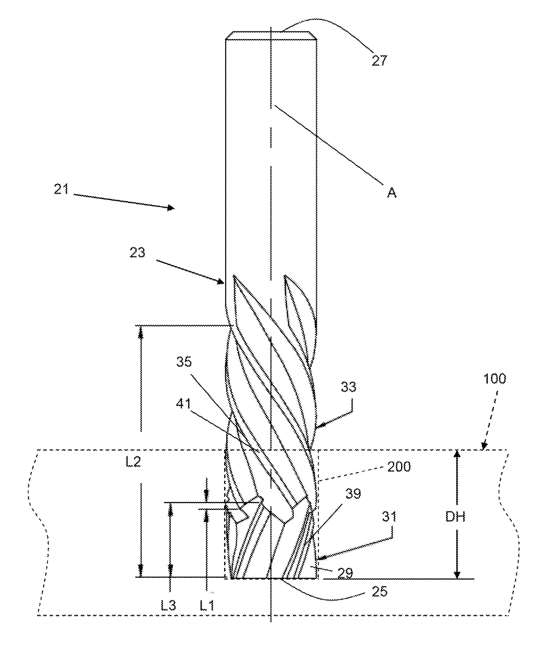
[0014]A rotating tool 21 according to an aspect of the present invention is shown in FIG. 1. The tool 21 is particularly useful as a compression cutting tool. The tool 21 comprises a tool body 23 comprising a first end 25 and a second end 27. The second end 27 typically forms part of a shank of the tool 21.

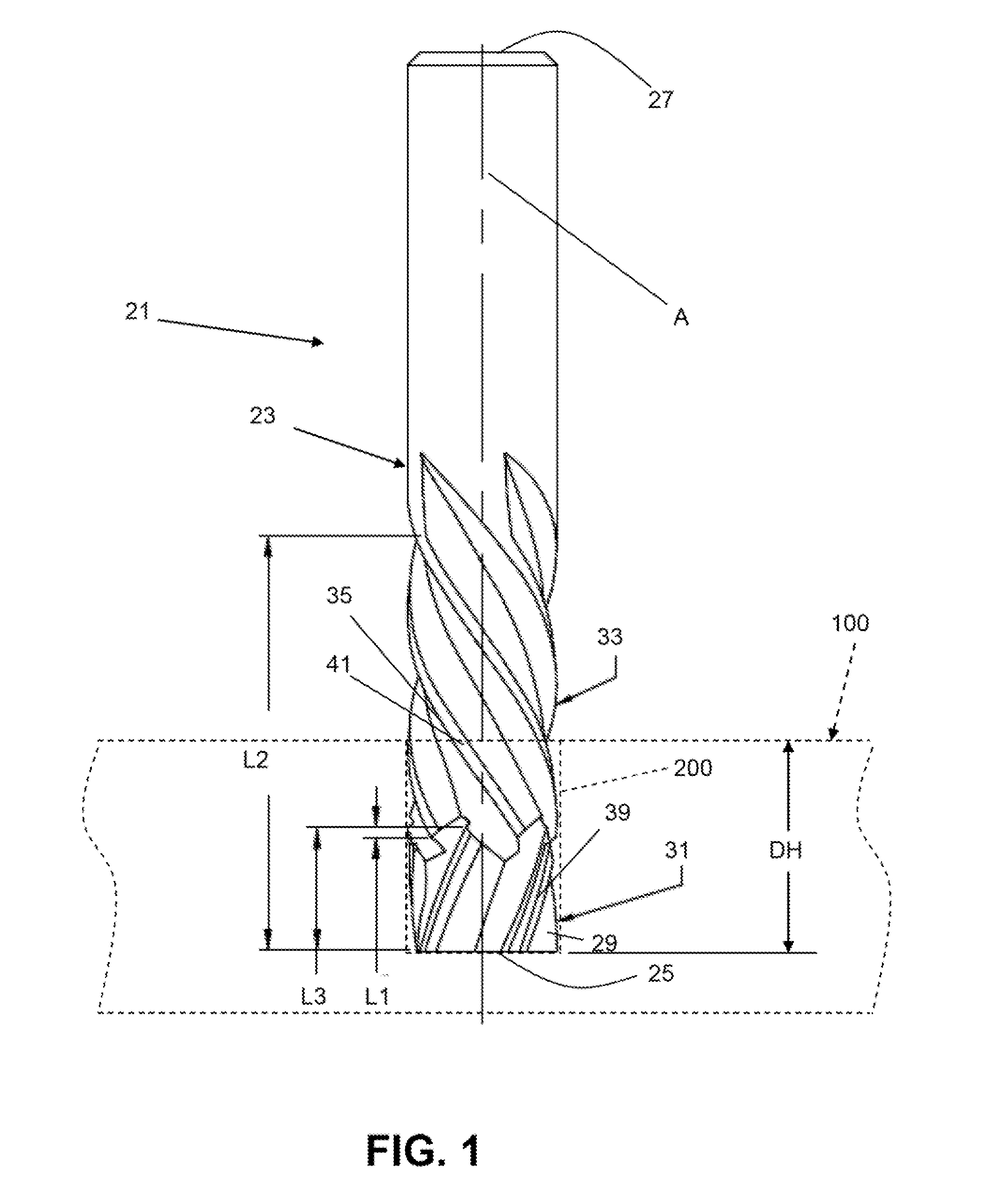
[0015]A plurality of first helical flutes 29 extend from the first end 25 of the tool body. The embodiment shown in FIG. 2 includes five flutes 29. Each first helical flute 29 of the plurality of helical flutes defines a respective first cutting edge 31.

[0016]As seen in FIG. 1, a plurality of second helical flutes 33 intersect with the first helical flutes 29 at non-zero distances from the first and the second ends 25 and 27 of the tool body 23 according to the length L1 of the first flute and the length L2 of the first and second flutes. Each second helical flute 33 of the plurality of second helical flutes defines a respective second cutting edge 35. Ordinarily, the second helic...


PUM

PropertyMeasurementUnit
diameteraaaaaaaaaa
diameteraaaaaaaaaa
diameteraaaaaaaaaa

Abstract

A rotating tool includes a tool body including a first end and a second end. A plurality of first helical flutes extend from the first end of the tool body, each first helical flute of the plurality of helical flutes defining a respective first cutting edge. A plurality of second helical flutes intersect with the first helical flutes at non-zero distances from the first and the second ends of the tool body, each second helical flute of the plurality of second helical flutes defining a respective second cutting edge. The first helical flutes and the second helical flutes are of opposite hands. The first helical flutes have a first pitch and the second helical flutes have a second pitch. A plurality of chip divider recesses are formed along each first cutting edge.

Description

BACKGROUND AND SUMMARY[0001]The present invention relates generally to cutting tools and, more particularly, to compression cutters.[0002]When machining a workpiece using a cutting tool with helical cutting edges and flutes, the workpiece will have a tendency to be pulled upward due to the helix of the tool. It is desirable to reduce this tendency.[0003]When machining materials having fibers, such as fiber reinforced composite materials, the fibers have a tendency to be pulled in a direction of the helix of the tool. Standard compression tooling tends to pull the fibers into the center of the workpiece. This promotes fiber pull out where the tool and workpiece meet. It is desirable to avoid this.[0004]According to an aspect of the present invention, a rotating tool comprises a tool body comprising a first end and a second end, a plurality of first helical flutes extending from the first end of the tool body, each first helical flute of the plurality of helical flutes defining a resp...

Claims


Application Information

Patent Timeline
Patent Type & Authority Applications(United States)
IPC IPC(8): B23C5/10B23P15/34
CPCB23C5/10B23C2210/32B23C2210/0457B23C2210/0492B23C2210/204B23C2210/486B23C2226/27B23B2226/275Y10T407/1948A61K31/573
Inventor WINEBRENNER, JOHN RICHARD
Owner SECO TOOLS AB
Why Eureka
Try Eureka