Core for a composite structure and method of fabrication thereof

a composite structure and core technology, applied in the direction of wind turbines with parallel air flow, liquid fuel engine components, wind energy generation, etc., can solve the problems of blade damage, impair the performance of the receptor, and affect the performance of the core, so as to facilitate the draping of the core, prevent excessive resin ingress, and increase flexibility/drapability

Active Publication Date: 2013-11-07
VESTAS WIND SYST AS
View PDF8 Cites 15 Cited by
  • Summary
  • Abstract
  • Description
  • Claims
  • Application Information

AI Technical Summary

Benefits of technology

[0036]The slits facilitate draping of the core to conform to the required curvature of the composite structure. Increased flexibility / drapability may be achieved by having slits that also extend at least partially through the other of the first or second core layers. The slits may be provided with or without removal of material from the core layers.
[0037]The slits may have a V-shaped cross section (also referred to herein as a “V-section”) or a cross-section that otherwise tapers inwards towards the ground plane. This may be desirable for preventing excessive resin ingress for a given drapability. For example, the movement capability of a V-section slit is similar to the movement capability of a parallel-sided slit having a slit opening of equivalent size. However, the volume of the V-section slit will be lower than the parallel-sided slit and so resin ingress is lower in the V-shaped slit whilst drapability of the core is similar.
[0038]The core may be of unitary construction, and may be in the form of discrete panels or sheets. The edges of the panels or sheets may be chamfered to provide chamfered joints between panels. Benefits of the chamfered edges are particularly acute when there is high drape. The split core design of the present invention results in improved RAM performance at core chamfers when compared to prior art single-layer cores, as described above with reference to FIGS. 4A and 4B.

Problems solved by technology

Whilst it was previously thought that penetrating the ground plane would impair its performance as a RAM reflector, it has now been realised that having a discontinuous ground plane does not necessarily result in impaired performance.
This tends to reduce the electric field around the lightning receptors in wind turbine blades, which can impair the performance of the receptors and may ultimately lead to the blades sustaining damage from a lightning strike.

Method used


Image

  • Core for a composite structure and method of fabrication thereof
  • Core for a composite structure and method of fabrication thereof
  • Core for a composite structure and method of fabrication thereof

Examples


Embodiment Construction

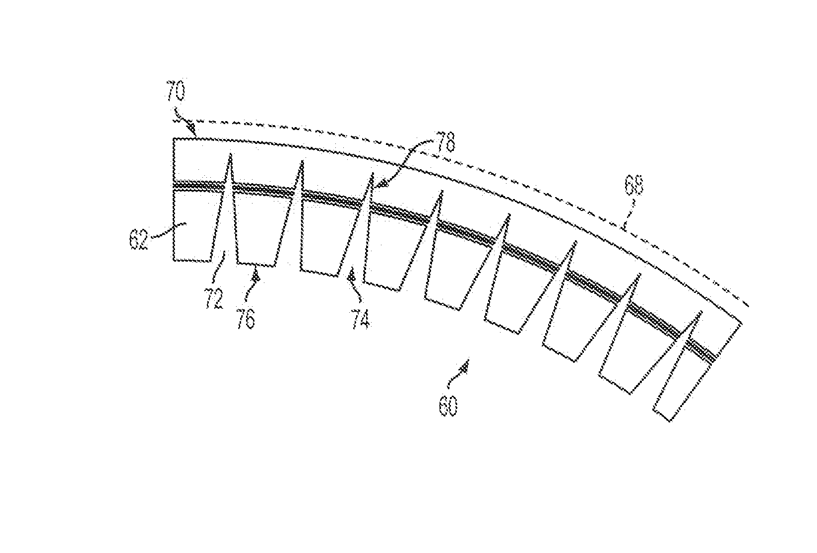
[0057]FIG. 5A shows a split core 60 in accordance with a first embodiment of the present invention for use in the construction of composite structures such as wind turbine blades. The split core 60 is of unitary construction and comprises an inner core layer 62 and an outer core layer 64, each made of polyethylene terephthalate (PET) or polyvinyl chloride (PVC) foam. A layer of carbon cloth 66, also known as ‘carbon veil’ is disposed between the inner and outer core layers 62, 64. The three layers 62, 64, 66 are bonded together by a suitable adhesive such that the carbon layer 66 is embedded within the resulting core 60. The embedded carbon layer 66 serves as a conductive ground plane.

[0058]Referring to FIG. 5B, the split core 60 is shown disposed inboard of an impedance layer 68. The impedance layer 68 is a circuit analogue (CA) layer, which comprises a carbon-ink circuit provided on a layer of plain weave E-glass. The impedance layer 68 is disposed close to an external surface (no...


PUM

PropertyMeasurementUnit
thicknessaaaaaaaaaa
thicknessaaaaaaaaaa
thicknessaaaaaaaaaa

Abstract

A flexible core (60) for a composite structure is described. The core includes a first core layer (62), a second core layer (64), and a ground plane (66) between the first and second core layers. A plurality of slits (72) is provided in the core, and each slit extends through one of the first of second core layers and through the ground plane. The core may be the core of a sandwich panel, for example a sandwich panel of the type used in the composite construction of wind turbine blades (10).

Description

FIELD OF THE INVENTION[0001]The present invention relates to radar absorbing materials (RAM) used in the construction of composite structures such as wind turbine blades. In particular, the present invention relates to sandwich panel cores incorporating RAM, and to composite structures incorporating such cores.BACKGROUND[0002]It is desirable to introduce radar absorbing material (RAM) into composite structures such as wind turbine components, for example wind turbine blades. One reason for this is that rotating blades have a radar signature similar to that of aircraft, which can make it difficult for air traffic control and other radar operators to distinguish between aircraft and wind turbines. Incorporating RAM into such structures ensures that the resulting structure has a reduced radar signature that can be distinguished easily from aircraft, and which creates less unwanted events (also known as “clutter”) on the screen of the radar operator.[0003]Existing wind turbine blades ar...

Claims


Application Information

Patent Timeline
Patent Type & Authority Applications(United States)
IPC IPC(8): F01D5/28H01Q17/00
CPCB29C70/086Y10T428/24314B29C70/882B29D99/0028B29L2031/085B32B38/1866B32B2309/105F03D1/065F05B2260/99H01Q17/008H01Q15/148H01Q17/007Y02E10/721F01D5/282B29C70/86Y02E10/72Y02P70/50F41H3/00H01Q17/00
Inventor APPLETON, STEVE
Owner VESTAS WIND SYST AS
Why Eureka
Try Eureka