Electronic vaporizing device and methods for use

a technology of electronic vaporizer and vaporizer chamber, which is applied in the direction of inhalators, tobacco, food science, etc., can solve the problems of variable operation, slow heat up time, and considerable drawbacks of conventional devices, and achieve the effect of improving heating and/or vaporizing capability

Inactive Publication Date: 2013-11-14
UPTOKE
View PDF13 Cites 843 Cited by
  • Summary
  • Abstract
  • Description
  • Claims
  • Application Information

AI Technical Summary

Benefits of technology

[0007]The present invention relates generally to electronic vaporizers, and more par...

Problems solved by technology

Although various electronic smoking and vaporizing devices currently exist in the market, conventional devices have considerable drawbacks.
Using chemical reactions to provide vaporizing heat has considerable shortcomings, which include frequent refilling of the butane source, inability to transport the devices (e.g. airplane travel), gaseous emissions from the butane reaction, the unpleasant scent associated with the chemical reaction, a slow heat up time due to the time required to transfer the heat to the heating element (e.g. a platinum element), and variability of operation, particularly at high altitudes.
Additionally, a chemical reaction cannot typically be easily or readily stopped to allow for rapid cooling.
Although the source of butane can be stopped, the reaction will generally continue until the butane already provided is spent; thus, heating units utilizing butane chemical reactions are not amenable to rapid heating or cooling, and include various drawbacks.
Vaporizing the solution by directly contacting the heating element often severely reduces the life of the heating element so that such devices often require frequent replacement, so much so that some such devices employ a disposable “cartomizer” which combines the heater and nicotine capsule into one piece.
Due to the difficulties associated wi...

Method used


Image

  • Electronic vaporizing device and methods for use
  • Electronic vaporizing device and methods for use
  • Electronic vaporizing device and methods for use

Examples


Embodiment Construction

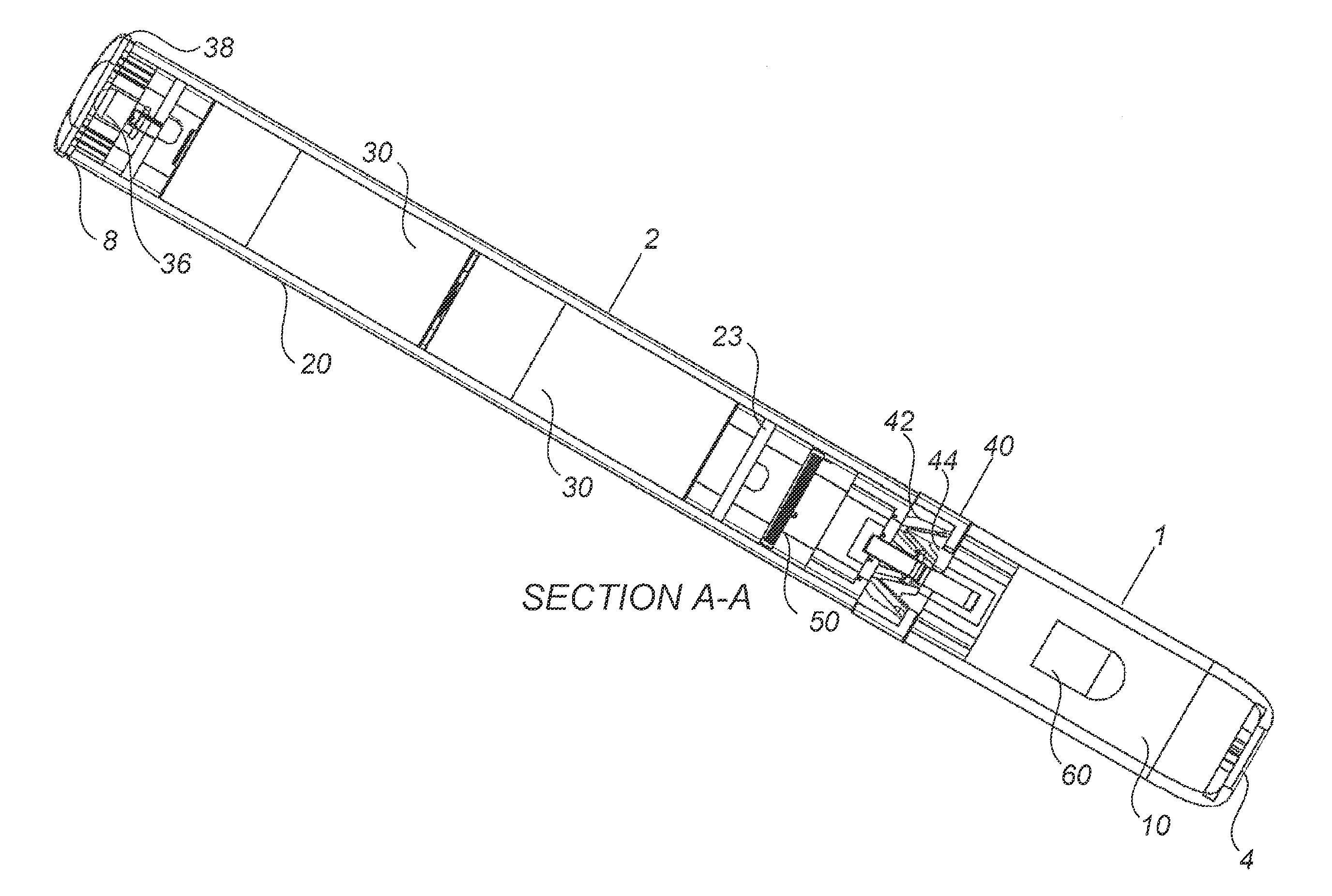
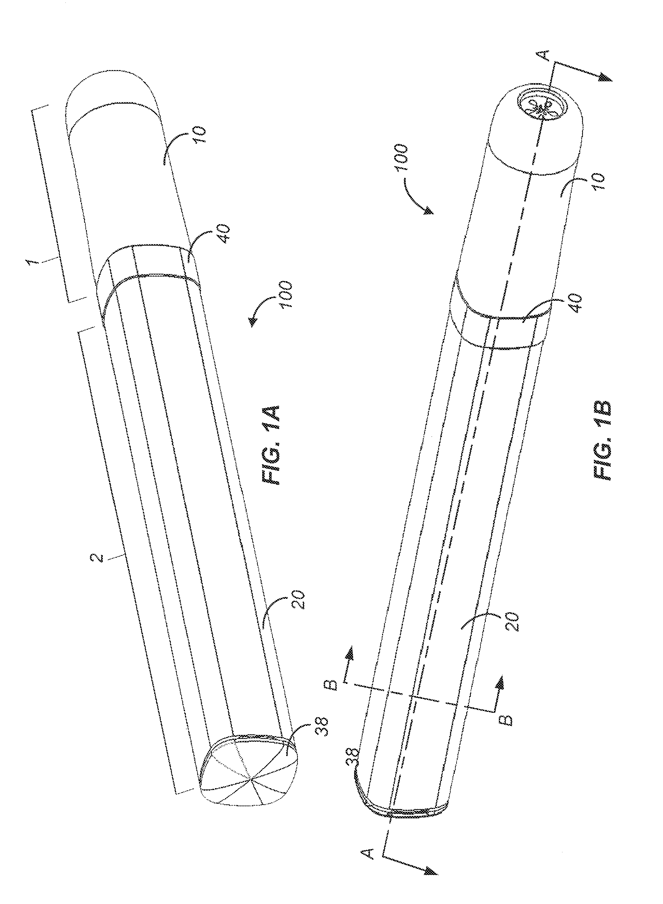
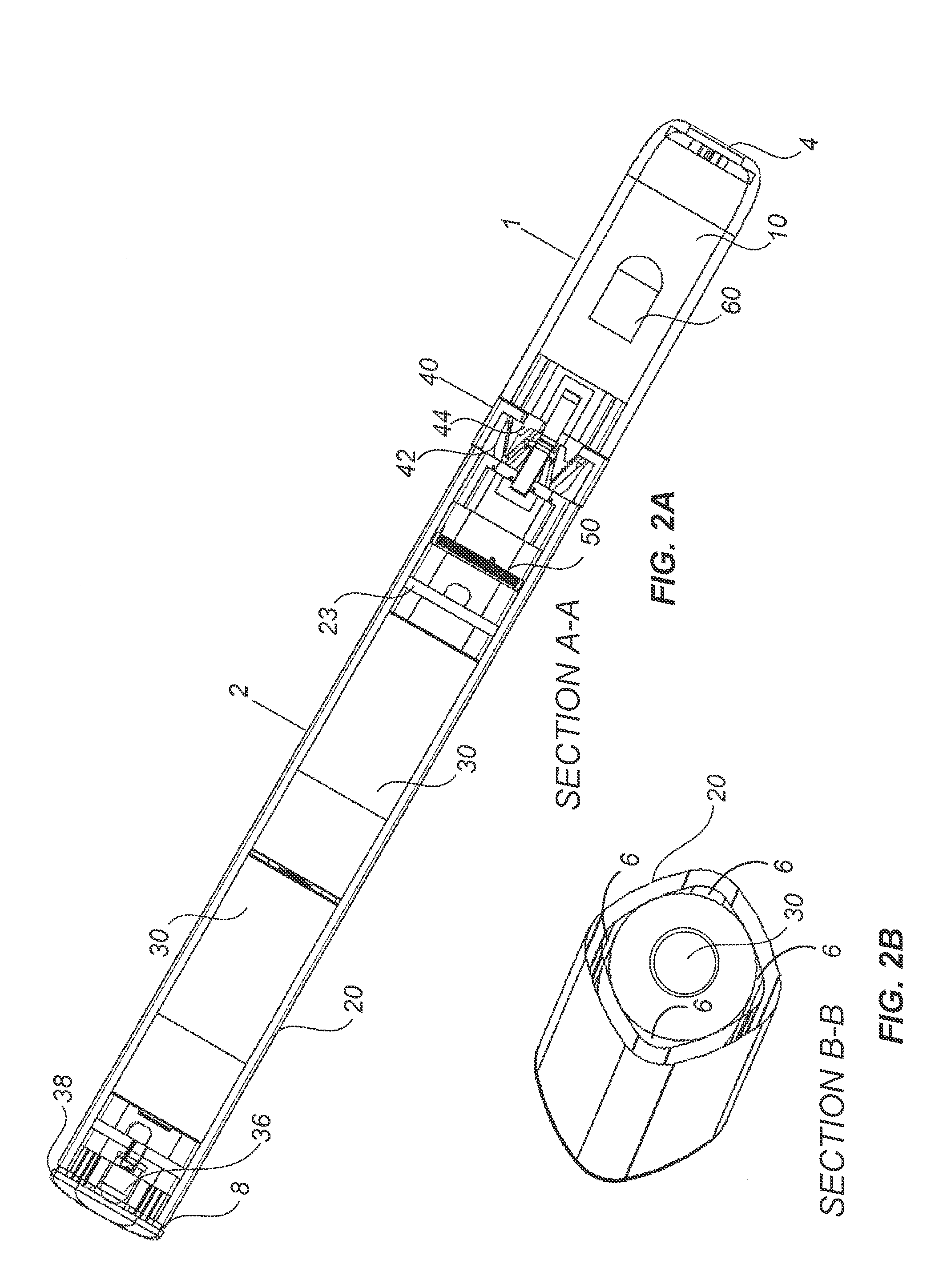
[0032]This invention relates generally to electronic vaporizing devices, and more particularly to a portable electronic vaporizing device having improved functionality and additional capabilities, as well as methods of vaporization and methods of use.

[0033]In an example embodiment, the invention provides a portable electronic vaporizing device having an outer shell housing internal components that facilitate heating and vaporizing of the selected substance disposed within for inhalation by a user. The device may be configured as a portable handheld device having an internal power source to allow for use over an extended period of time and / or use on multiple occasions without requiring recharging or replacement of the power source. The device is further configured to provide improved functionality, increased capabilities, and an enhanced “smoking” (more accurately inhalation of vapor) experience when compared to conventional electronic smoking and vaporizing devices. In certain aspec...


PUM


Abstract

Devices and methods for vaporizing active ingredients of a selected substance for inhalation using a portable vaporization device are provided herein. In certain aspects, the device includes a portable power source, a heating portion, an inhalation sensor, a temperature sensor, a distal light source, and a grinding portion. In response to an inhalation by a user, the power source energizes a heating element of the heating portion so as to heat air flow to a desired vaporization temperature within a few seconds of detecting inhalation, using convection and radiative heating. The device may include a receptacle for receiving a cartridge containing a pre-prepared substance, such as a liquid, gel, powder, or solid brick, and a grinding portion to allow a user to grind intact portions of cellulose-based material into smaller pieces to facilitate vaporization by manually rotating portions of the device relative to each other.

Description

CROSS-REFERENCES TO RELATED APPLICATIONS[0001]This application is a Non-Provisional Application of and claims priority to U.S. Provisional Application No. 61 / 609,813, filed on Mar. 12, 2012, the entire contents of which are incorporated herein by reference.BACKGROUND OF THE INVENTION[0002]The present invention generally relates to an electronic vaporizing device, and in particular to an electronic vaporizing device having improved functionality and increased capability.[0003]Although various electronic smoking and vaporizing devices currently exist in the market, conventional devices have considerable drawbacks. For example, many conventional portable smoking and vaporizing devices have heating units that utilize chemical reactions to provide sufficiently rapid heating, for example a catalytic heater. A catalytic heater generates heat through a flameless catalytic reaction involving butane (or propane) and oxygen; the heat is generated by bringing the butane and oxygen from the air ...

Claims


Application Information

Patent Timeline
IPC IPC(8): A24F47/00A24F40/00A24F40/46A24F40/51A24F40/60A24F40/90
CPCA24F47/008A24F40/00A24F40/46A24F40/51A24F40/60A24F40/90A61M15/06
Inventor LEVIN, JASON R.TAVIN, ADAM J.MISHIN, ARTEMWILSON, HOWARD ALLENSAHU, SAROJ KUMARJUMA, JAMES
Owner UPTOKE
Why Eureka
Try Eureka