Clutch backer plate with recessed rivets

a technology of backer plate and rivet, which is applied in the direction of friction clutch, friction lining, etc., can solve the problems of increasing the high cost of the backing plate, so as to achieve the effect of reducing the thickness of the friction button and reducing the cost of the drive disc assembly

Inactive Publication Date: 2013-11-14
EATON CORP
View PDF6 Cites 3 Cited by
  • Summary
  • Abstract
  • Description
  • Claims
  • Application Information

AI Technical Summary

Benefits of technology

[0007]To meet the above-noted and other desires, a revelation of the present invention is brought forth. The present invention brings forth a driven disc assembly wherein the clutch disc has enlarged holes for connection of the backing plates. The backing plates have semi-pierced sections that are insertable within the clutch disc holes. The thickness of the backing plates are enlarged from their normal thickness causing a top surface of the backing plates to axially clear the head of a conventional rivet. The thickness of the friction buttons can then be reduced to their minimal effective thickness.

Problems solved by technology

Typically, the ceramic material making up the button is a very expensive material that typically far exceeds the cost of the backing plate 19.
However, since the overall thickness 29 of the driven disc assembly is determined by other design criteria, the recessed design of driven disc assembly 41 mandates even thicker buttons 48 (to achieve an overall axial thickness 29) thereby providing a button with more excess material which cannot be utilized (due to clutch design) and thereby increasing driven disc assembly cost.

Method used


Image

  • Clutch backer plate with recessed rivets
  • Clutch backer plate with recessed rivets
  • Clutch backer plate with recessed rivets

Examples


Embodiment Construction

[0022]The following description of the preferred embodiment(s) is merely exemplary in nature and is in no way intended to limit the invention, its application, or uses.

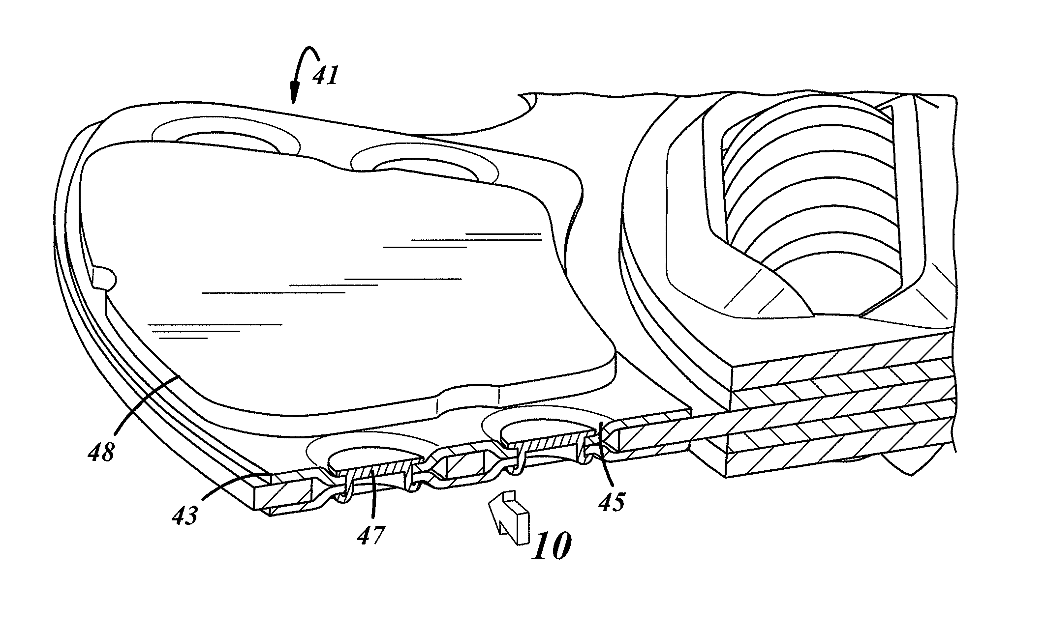
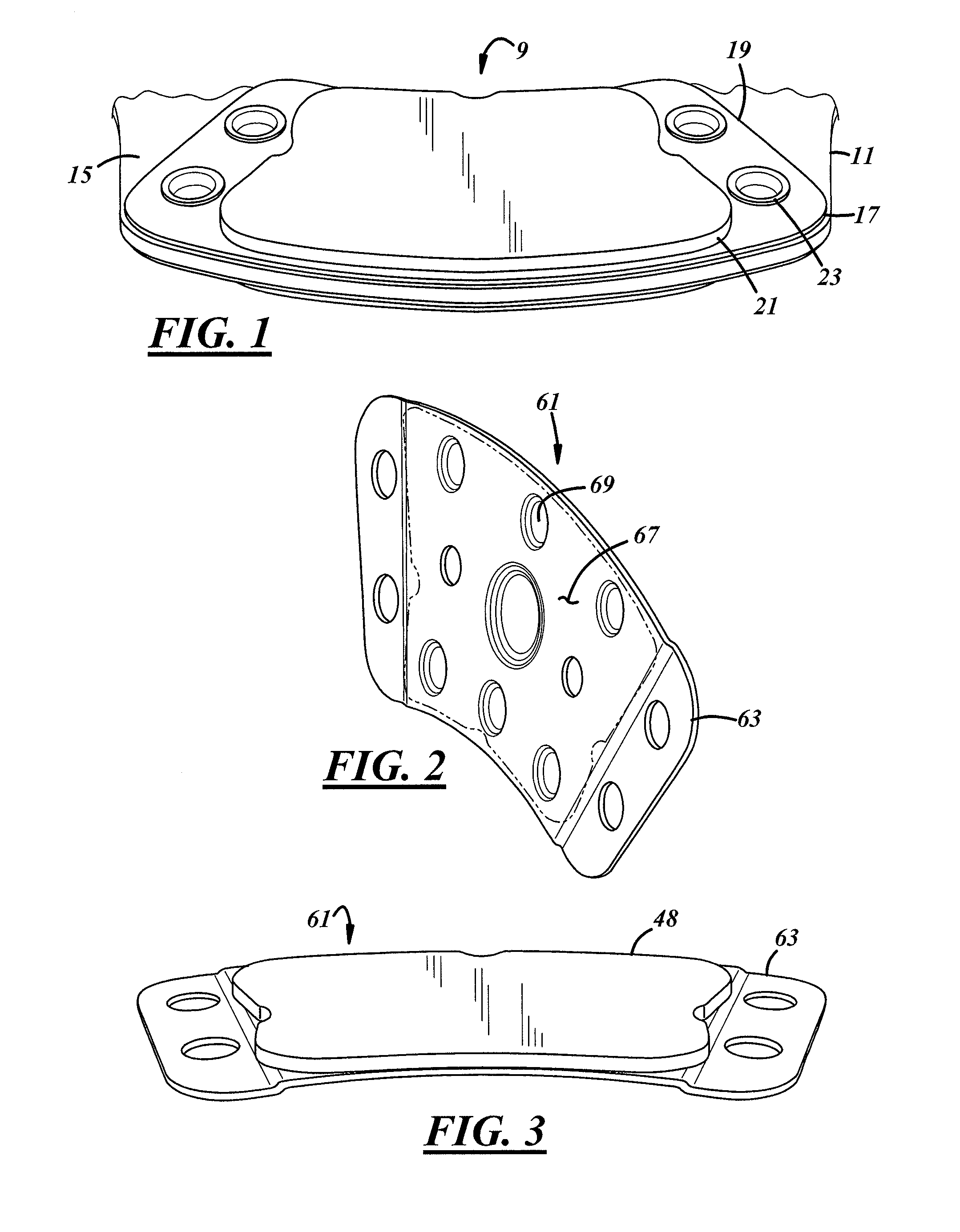
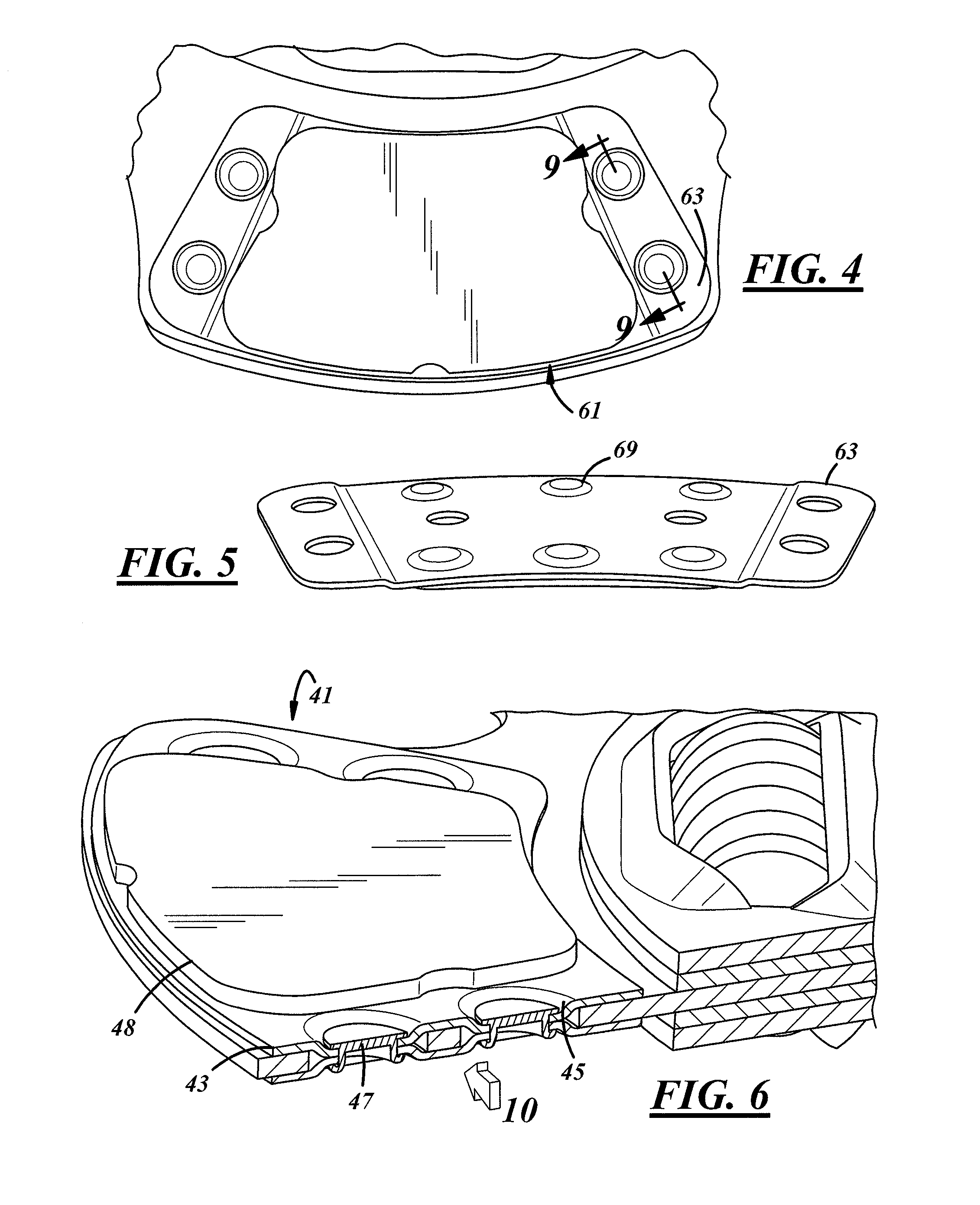
[0023]Referring to FIGS. 8 and 12, an inventive low profile button dual face clutch friction plate or disc driven assembly 107 has an overall axial width 29. The disc driven assembly 107 has a disc 111. The disc 111 has a series of mounting holes 114, which are enlarged in comparison to the mounting holes shown formed in the disc drive assembly 9 disc 11. However, in other aspects, the disc 111 is essentially identical to the disc 11. A backing plate 116 is provided which typically has a greater thickness 136 (typically a total thickness between 0.080 and 0.110 inches) than the backing plates previously described. The backing plate 116 has a mounting hole 118. Hole 118 is smaller in diameter then the disc hole 114 and is aligned therewith. The hole 118 is surrounded by a stamped semi-pierced section 120. An axially in...


PUM


Abstract

A driven disc assembly is provided wherein a clutch disc has enlarged holes for connection of opposing backing plates. The backing plates have semi-pierced sections that are insertable within mounting holes of the clutch disc. The thickness of the backing plates are enlarged from their normal thickness causing a top surface of the backing plates to axially clear heads of conventional rivets. The thickness of the friction buttons on the backing plates can then be reduced to their minimal effective use thickness.

Description

FIELD OF THE INVENTION[0001]The field of the present invention is that of friction or driven disc assemblies. The present invention is particularly applicable in driven disc assemblies in clutches utilized to selectively connect an engine of a motorized vehicle with a transmission of the motorized vehicle, especially vehicles such as large trucks.BACKGROUND OF THE INVENTION[0002]Many large motorized vehicles have a clutch assembly to selectively connect an engine of the vehicle with the vehicle transmission. The workings of such a clutch assembly can be discovered by a review of U.S. patent application Ser. No. 12 / 807,971, Franke, entitled Dry Clutch Having Solid Lubricant Friction Stabilization Inserts, filed Sep. 17, 2010 (the disclosure of which is incorporated by reference herein). Referring to FIGS. 1, 7 and 11, a conventional driven disc assembly 9 includes a disc member 11. The disc member 11 is torsionally connected with a damper unit 13 which spring dampens torsional vibrat...

Claims


Application Information

Patent Timeline
Patent Type & Authority Applications(United States)
IPC IPC(8): F16D13/64
CPCF16D13/64F16D2069/0433
Inventor ALLMANDINGER, TIMOTHY BERNARDFRANKE, BRIAN WILLIAMBARNHOLT, MARK CHARLES
Owner EATON CORP
Why Eureka
Try Eureka