Integrated magnetoresistive sensor, in particular three-axis magnetoresistive sensor and manufacturing method thereof

Active Publication Date: 2013-11-14
STMICROELECTRONICS SRL
View PDF6 Cites 51 Cited by
  • Summary
  • Abstract
  • Description
  • Claims
  • Application Information

AI Technical Summary

Problems solved by technology

In fact, in this case, the operations of assembly are much more complex and the finished device is much more costly.
In addition, with the scaling down of the chips, the packages should be increasingly small (e.g., from 5×5 mm2 to 3×3 mm2); however, vertical assemblage is incompatible with the desired reduction.
The solutions proposed to the problem indicated are not, however, satisfactory.
On the other hand, this solution renders more difficult deposition and definition of the transversal strips or “barber pole

Method used


Image

  • Integrated magnetoresistive sensor, in particular three-axis magnetoresistive sensor and manufacturing method thereof
  • Integrated magnetoresistive sensor, in particular three-axis magnetoresistive sensor and manufacturing method thereof
  • Integrated magnetoresistive sensor, in particular three-axis magnetoresistive sensor and manufacturing method thereof

Examples


Embodiment Construction

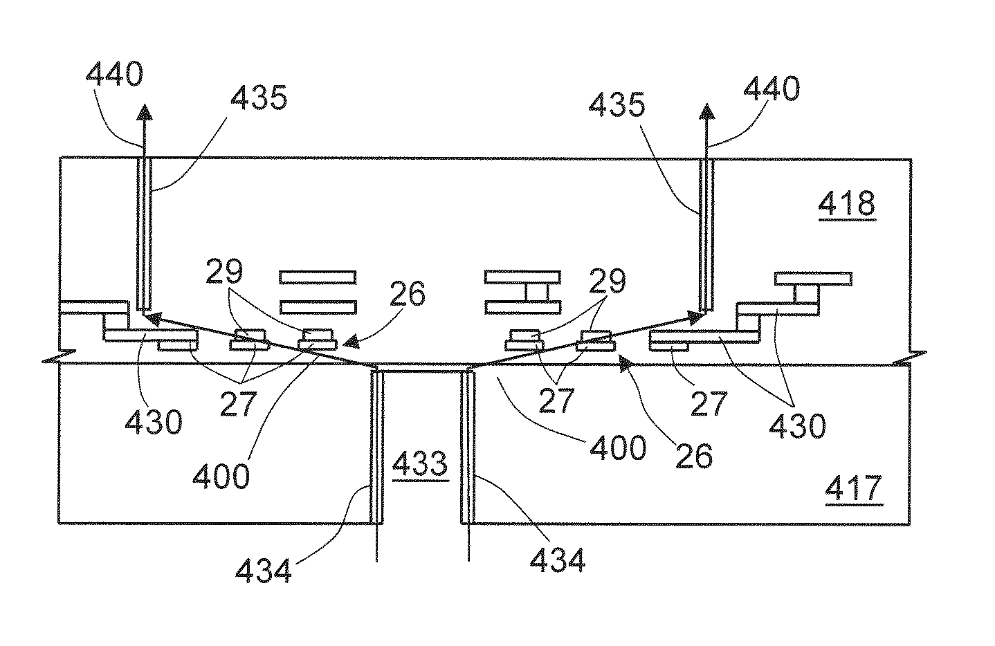
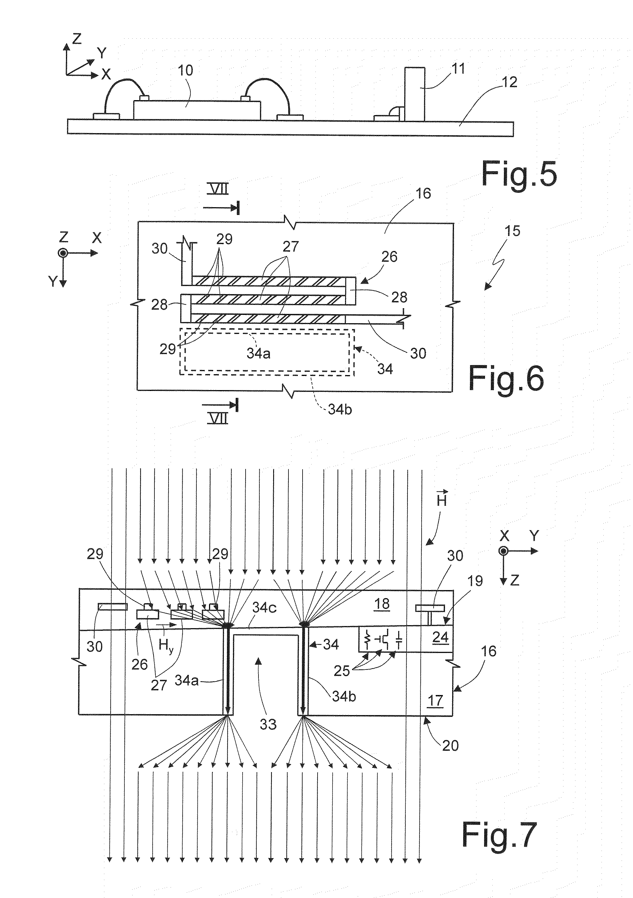
[0049]FIGS. 6 and 7 show a magnetoresistive sensor 15 formed in a chip 16 comprising a substrate 17 of conductive material, for example silicon, and an insulating layer 18, for example, of silicon oxide, typically including a plurality of layers arranged on top of each other. The substrate 17 has a front surface 19 covered by the insulating layer 18 and a rear surface (back) 20. The front surface 19 and the rear surface 20 extend parallel to the plane XY. At least one active area 24 may be present within the substrate 17 and may accommodate electronic components 25, shown only schematically.

[0050]The insulating layer 18 accommodates a magnetoresistor 26, for example an anisotropic magnetoresistor AMR, of a planar type, extending parallel to the plane XY and to the surfaces 19, 20 and thus defines a sensitivity plane. In the example illustrated, the magnetoresistor 26 is formed by a plurality of magnetoresistive strips 27, for example of permalloy (Ni / Fe), connected at the ends by co...


PUM


Abstract

An integrated magnetoresistive device, where a substrate of semiconductor material is covered, on a first surface, by an insulating layer. A magnetoresistor of ferromagnetic material extends in the insulating layer and defines a sensitivity plane of the sensor. A concentrator of ferromagnetic material including at least one arm, extending in a transversal direction to the sensitivity plane and vertically offset to the magnetoresistor. In this way, magnetic flux lines directed perpendicularly to the sensitivity plane are concentrated and deflected so as to generate magnetic-field components directed in a parallel direction to the sensitivity plane.

Description

CROSS REFERENCE TO RELATED APPLICATIONS[0001]This application is a U.S. National Stage patent application based on International patent application number PCT / EP2011 / 074045, filed Dec. 23, 2011, which claims the priority benefit of Italian patent application number TO10A001050, filed Dec. 23, 2010, which applications are hereby incorporated by reference to the maximum extent allowable by law.BACKGROUND[0002]1. Technical Field[0003]The present disclosure relates to an integrated magnetoresistive sensor, in particular a three-axis magnetoresistive sensor, and to the manufacturing process thereof. In the following description, particular reference will be made to an anisotropic magnetoresistive (AMR) sensor, without, however, being limited thereto, and embodiments are applicable also to other types of magnetoresistive sensors, such as the giant-magnetoresistive (GMR) sensor and tunneling-magnetoresistive (TMR) sensor and other integrated magnetic-field sensors in themselves sensitive t...

Claims


Application Information

Patent Timeline
IPC IPC(8): G01R33/00H01L43/12
CPCG01R33/0011H01L43/12B82Y25/00G01R33/093G01R33/096G01R33/098G01R33/0052H10B61/00H10N59/00H10N50/01H10N50/10G01R33/09G01R33/0206
Inventor PACI, DARIOMORELLI, MARCORIVA, CATERINA
Owner STMICROELECTRONICS SRL
Why Eureka
Try Eureka