
Drying method

a technology of textile fibres and fabrics, applied in the direction of drying, lighting and heating apparatus, furniture, etc., can solve the problems of high energy consumption, significantly less efficient tumble drying than washing, and high energy consumption in industrial tumble drying. achieve excellent drying performance, improve drying time, and reduce energy consumption

Active Publication Date: 2013-11-21
XEROS LTD
View PDF15 Cites 15 Cited by
  • Summary
  • Abstract
  • Description
  • Claims
  • Application Information

AI Technical Summary

Benefits of technology

The present invention provides a method for drying a wet substrate using a solid particulate material at ambient or elevated temperature. This treatment is carried out in a rotating drum with perforated side walls, which facilitates increased mechanical action between the substrate and the particulate material. This method allows for excellent drying performance at reduced temperatures (lower energy consumption), while achieving the same level of drying performance as prior art processes. The drying operations are typically carried out at temperatures that are 20°C lower than with prior art processes.

Problems solved by technology

However, such processes, though generally very effective, are usually characterised by high levels of energy consumption, both in terms of effecting rotation of the container and, most particularly, in generating heated air.
Energy consumption in industrial tumble drying is usually higher, due to the need for faster cycle times. It is also noteworthy that, overall, tumble drying is significantly less efficient than washing as a component part of the laundry process in either sector.
This results in release and evaporation of water from within the fabric, and hence drying.
Creasing, which concentrates stresses during this drying process, is a major source of localised fabric damage.
Ironing at high temperatures is then the conventional means used to remove such creasing and this, too, brings a fabric damage penalty.

Method used


Image

  • Drying method
  • Drying method
  • Drying method

Examples


example 1

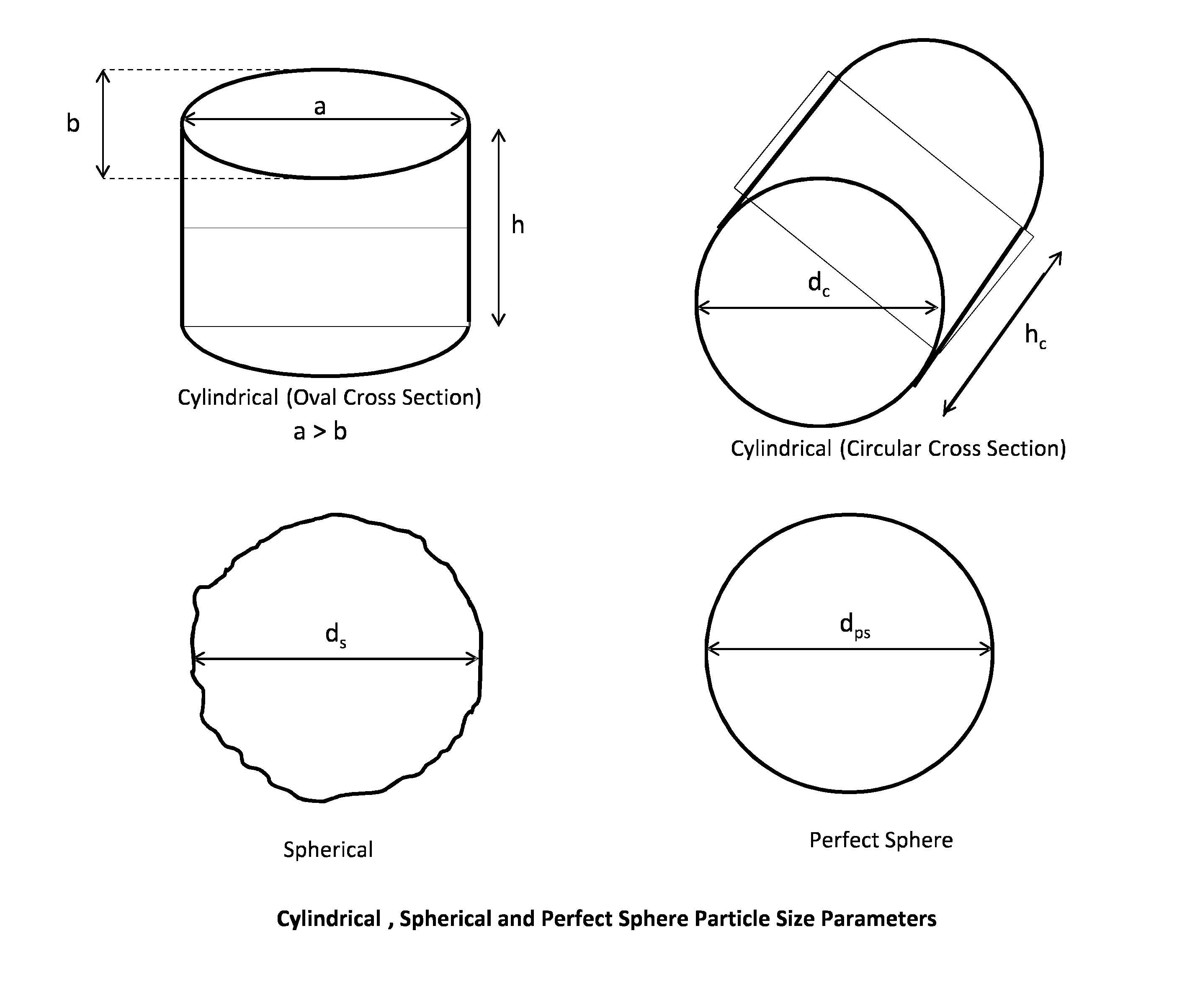
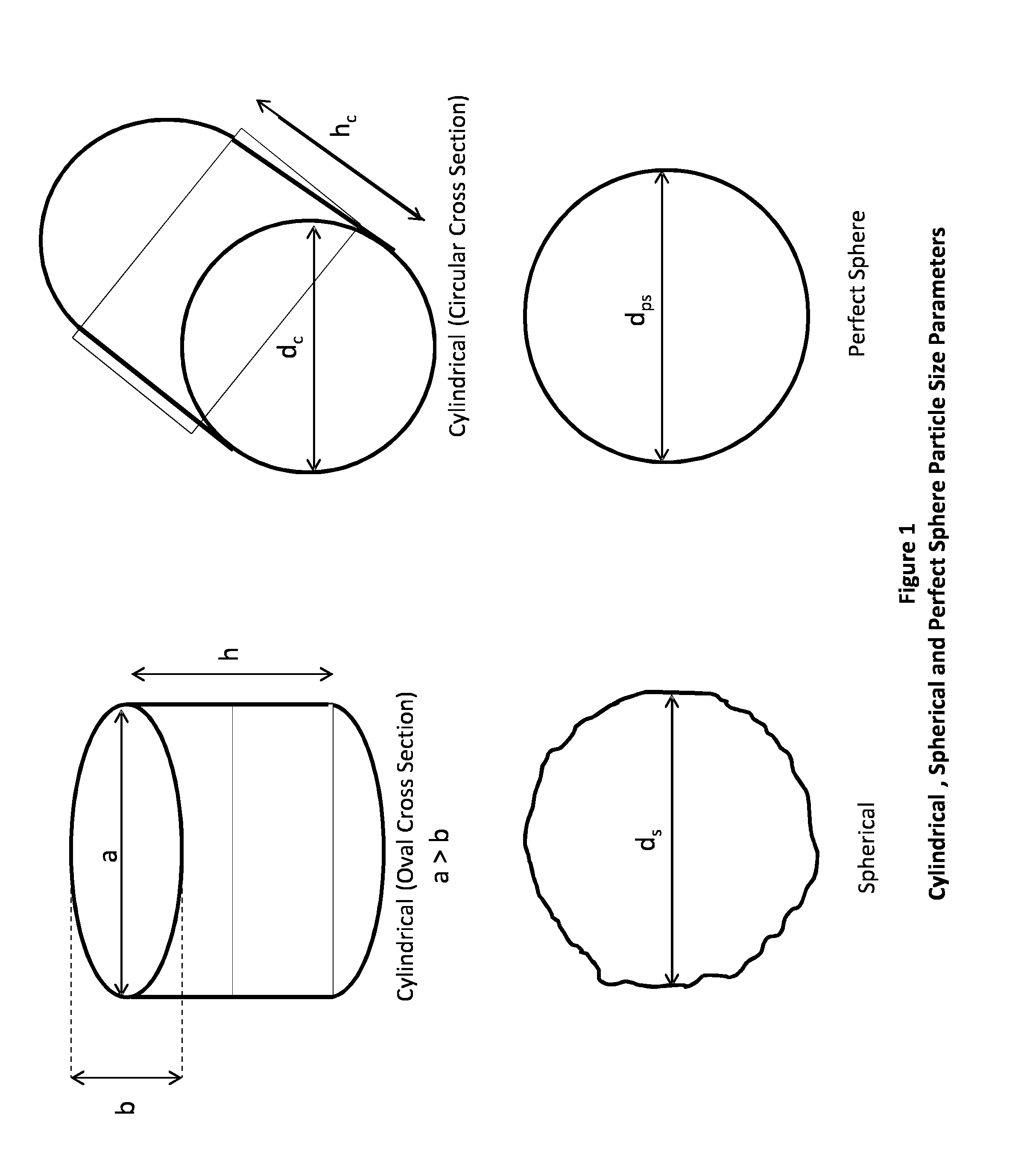
[0083]A drying procedure was carried out by adding a solid particulate material comprising 4 kg of Nylon 6,6 particles (DuPont Zytel® 101 NC010) to a mesh bag with 1 kg (dry mass) of a cloth substrate, which had been wetted with 10° C. water. Details of the particles are set out in Table 1 and an illustration of these cylindrical particles is provided in FIG. 1.

TABLE 1PARTICULATE MATERIALParticleParticleParticleabhVolumeDensityMassParticle TypeParticle Shape(mm)(mm)(mm)(mm3)(g / cm3)(mg)DuPont Zytel ® 101 NC010Cylindrical (Oval2.51.83.110.51.112(Nylon 6,6)Cross Section)

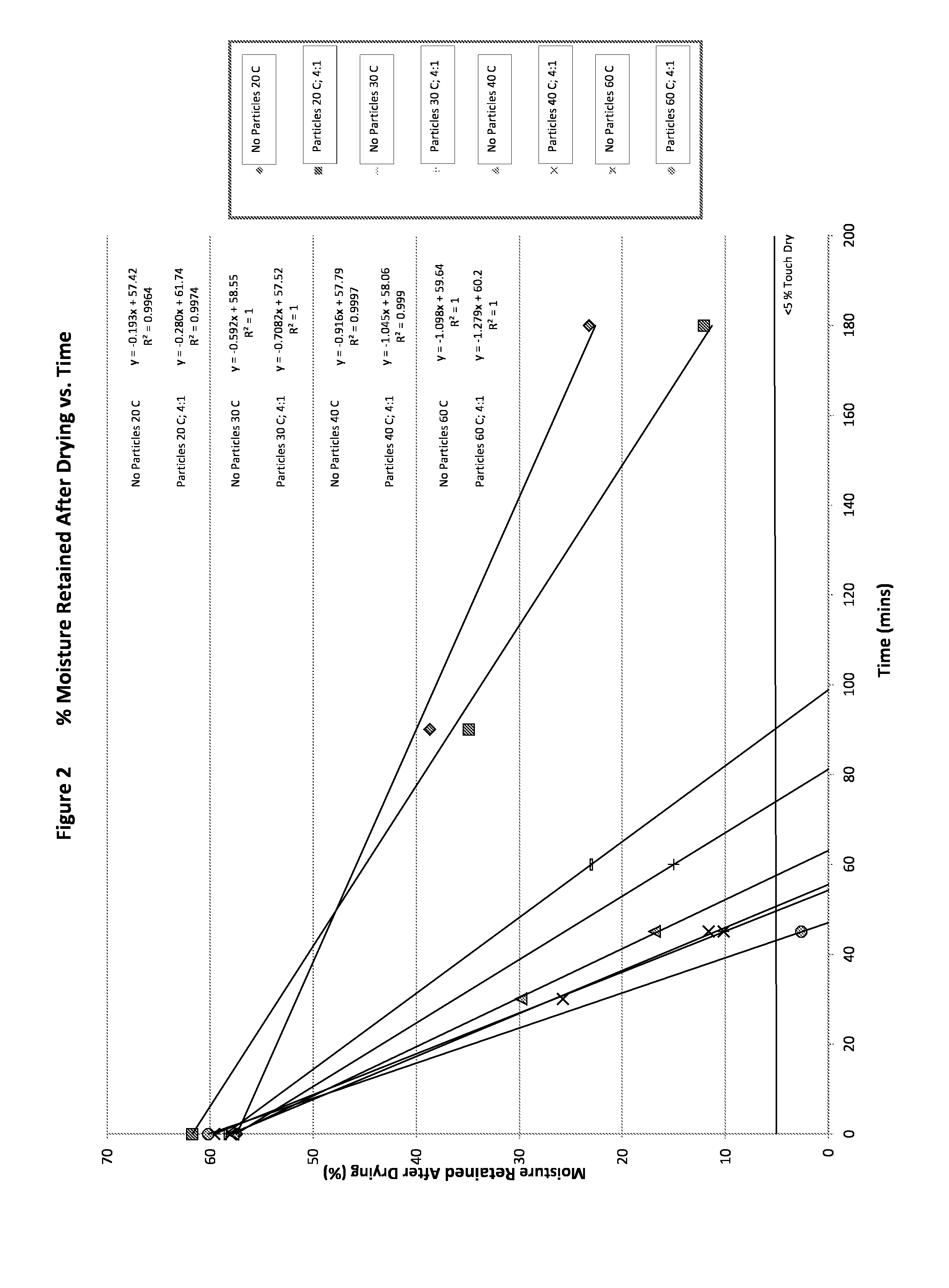
[0084]The substrate was made up of the same type of article in each case (cotton pillowcases). This bag was then loaded into a conventional commercial vented tumble dryer (Danube™—Model Number TD 2005 / 10E). The dryer was set to rotate at 48 rpm which, with a drum diameter of 74 cm, resulted in a centripetal force on the bag and its contents of 0.95 G. The dryer operating temperature was set to 20°, 30°, 40°, or 60° C. f...

example 2

[0086]Table 3 and FIG. 3 provide a comparative illustration of the drying efficacy which is achieved when heated particles are employed. These data effectively provide an illustration of the benefits associated with heat retention in the particles for a subsequent drying process. Here, however, the particles were pre-heated in a separate tumble dryer to 60° C. (measured by an in-situ remote temperature recorder) in order to simulate heated particles from a previous cycle. These hot particles were then quickly added to the mesh bag with wet cloth as before, and tumbled in the Danube™ dryer at 20° C. (the test denoted ‘Particles 60° C. / Dryer 20° C.’). As previously therefore, this was effectively ambient temperature with the heaters in the dryer switched off. With heated particles, the drying efficiency increased to 0.48% water removed / minute, vs. the test from Example 1 with the particles at 20° C., which gave only 0.28% water / min.

TABLE 3DRYING TEST RESULTSDrying Time to 5%Drying Rat...


PUM


Abstract

The invention provides a method for the drying of a wet substrate, the method comprising treating the substrate with a solid particulate material at ambient or elevated temperature, the treatment being carried out in an apparatus comprising a drum comprising perforated side walls, wherein the drum comprising perforated side walls is rotated so as to facilitate increased mechanical action between the substrate and the particulate material. Preferably, the drum comprising perforated side walls has a capacity of between 5 and 50 litres for each kg of fabric in the load and is rotated at a speed which generates G forces in the range of from 0.05 to 0.99 G, and the method is carried out at a temperature of between 5° and 120° C. Preferably, the solid particulate material comprises a multiplicity of particles at a particle to fabric addition level of 0.1:1-10:1 by mass, wherein the particles comprise polymeric particles, non-polymeric particles, or mixtures of polymeric and non-polymeric particles. All particles may be solid or hollow in their structure, have smooth or irregular surface features, and are of such a shape and size as to allow for good flowability and intimate contact with the wet substrate. The invention provides optimum drying performance as a result of improved mechanical interaction between substrate and particulate media and is preferably used for the drying of textile fabrics. The method allows for significant reduction in the consumption of energy when compared with the conventional tumble drying of textile fabrics, and also facilitates reduced textile fabric damage.

Description

FIELD OF THE INVENTION[0001]The present invention relates to the drying of textile fibres and fabrics in a tumble dryer using a system which utilises only limited quantities of energy, and which reduces drying-related creasing and associated textile fabric damage. Specifically, the invention provides a method adapted for use in this context.BACKGROUND TO THE INVENTION[0002]Tumble drying processes are a mainstay of both domestic and industrial textile fabric cleaning procedures and typically involve placing the textiles in a container such as a perforated cylindrical drum which is rotated in alternating clockwise and anti-clockwise cycles whilst hot air is introduced into the drum through the perforations. A combination of the hot air treatment and the mechanical action of the tumbling process causes water to be expelled from the textile materials in order that drying is achieved.[0003]However, such processes, though generally very effective, are usually characterised by high levels ...

Claims


Application Information

Patent Timeline
Patent Type & Authority Applications(United States)
IPC IPC(8): F26B3/02
CPCF26B3/02D06F58/02F26B3/205D06F2103/34D06F2103/44D06F2105/46D06F58/30D06F58/20D06F2103/08D06F2103/38
Inventor JENKINS, STEPHEN DEREKKENNEDY, FRAZER JOHNBURKINSHAW, STEPHEN MARTIN
Owner XEROS LTD
Learn More