Method and device for exhaust gas management

a technology of exhaust gas management and exhaust inserts, applied in the direction of engines, mechanical equipment, machines/engines, etc., can solve the problems of poor engine performance, exhaust inserts that would produce detrimental effects on stock exhaust systems, etc., and achieve the effect of increasing horsepower

Inactive Publication Date: 2013-11-21
EGM TECH
View PDF12 Cites 0 Cited by
  • Summary
  • Abstract
  • Description
  • Claims
  • Application Information

AI Technical Summary

Benefits of technology

[0005]Exemplary embodiments of the inventive concept are based on the unexpected results achieved and features discovered when attempting to incorporate exhaust inserts into original manufacturer exhaust systems. While exhaust inserts were used to increase horsepower in race cars with headers specifically designed for inclusion of an exhaust insert it was believed, by those skilled in the art, that exhaust i

Problems solved by technology

While exhaust inserts were used to increase horsepower in race cars with headers specifically designed for inclusion of an exhaust insert it was believed, by those skilled in the art, that exhaust inserts would produce detrimental results when applied to stock exhaust systems.
Those of ordinary skill in the art cited several reasons including throttle conditions, differing computer systems and the physical length of racing headers which are much longer and tuned differently from stock exhaust manifolds for the expectation that exhaust inserts would produce a detrimental effect on stock exhaust systems.
Those of ordinary skill in the art believed insertion of an exhaust insert would cause poor engine performance and result

Method used


Image

  • Method and device for exhaust gas management
  • Method and device for exhaust gas management
  • Method and device for exhaust gas management

Examples


Embodiment Construction

)

[0031]The inventive concept will now be described more fully hereinafter with reference to the accompanying drawings, through which some, but not all possible embodiments of the invention are shown. Indeed, the inventive concept may be embodied in various forms and should not be construed as limited to the particular embodiments set forth herein.

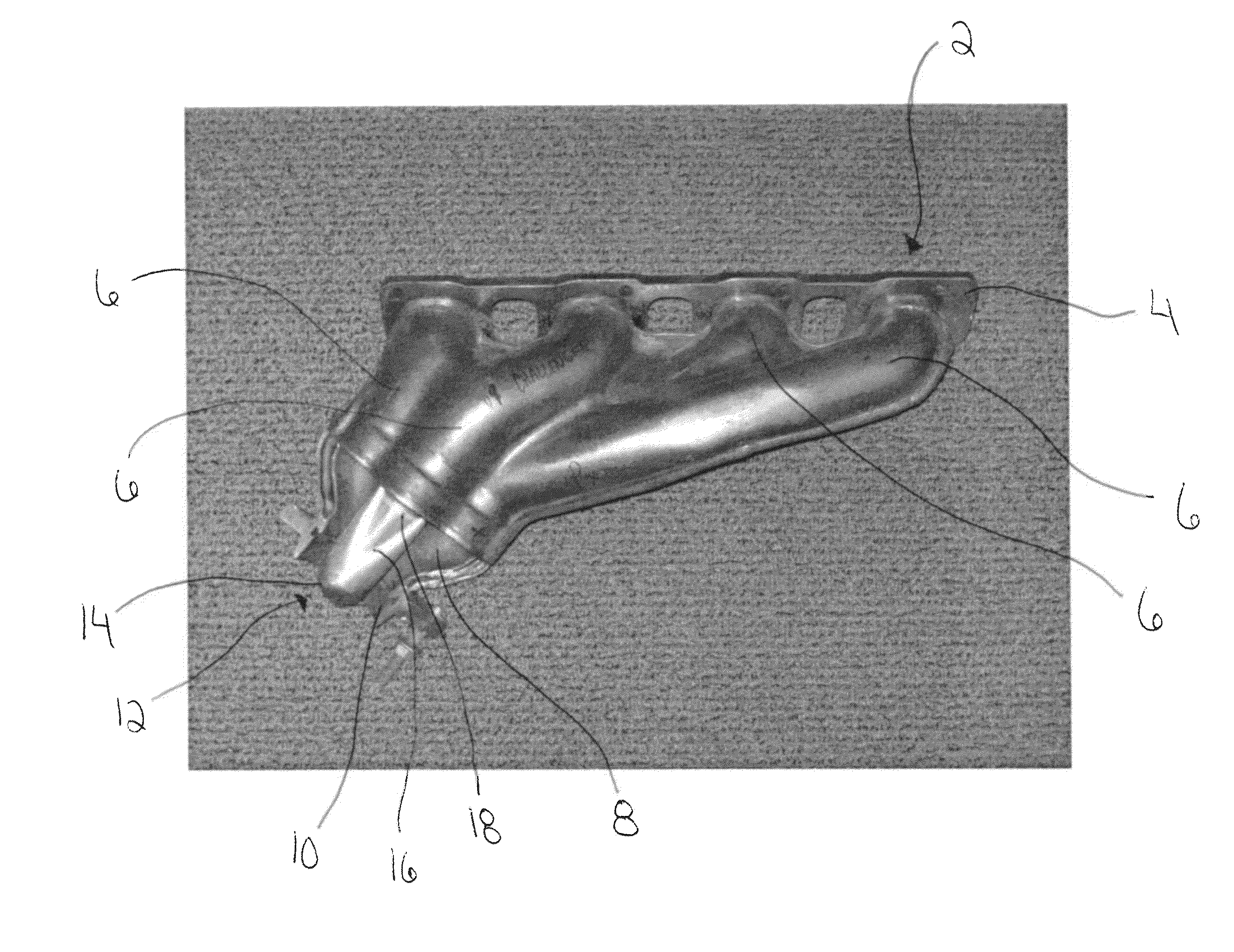
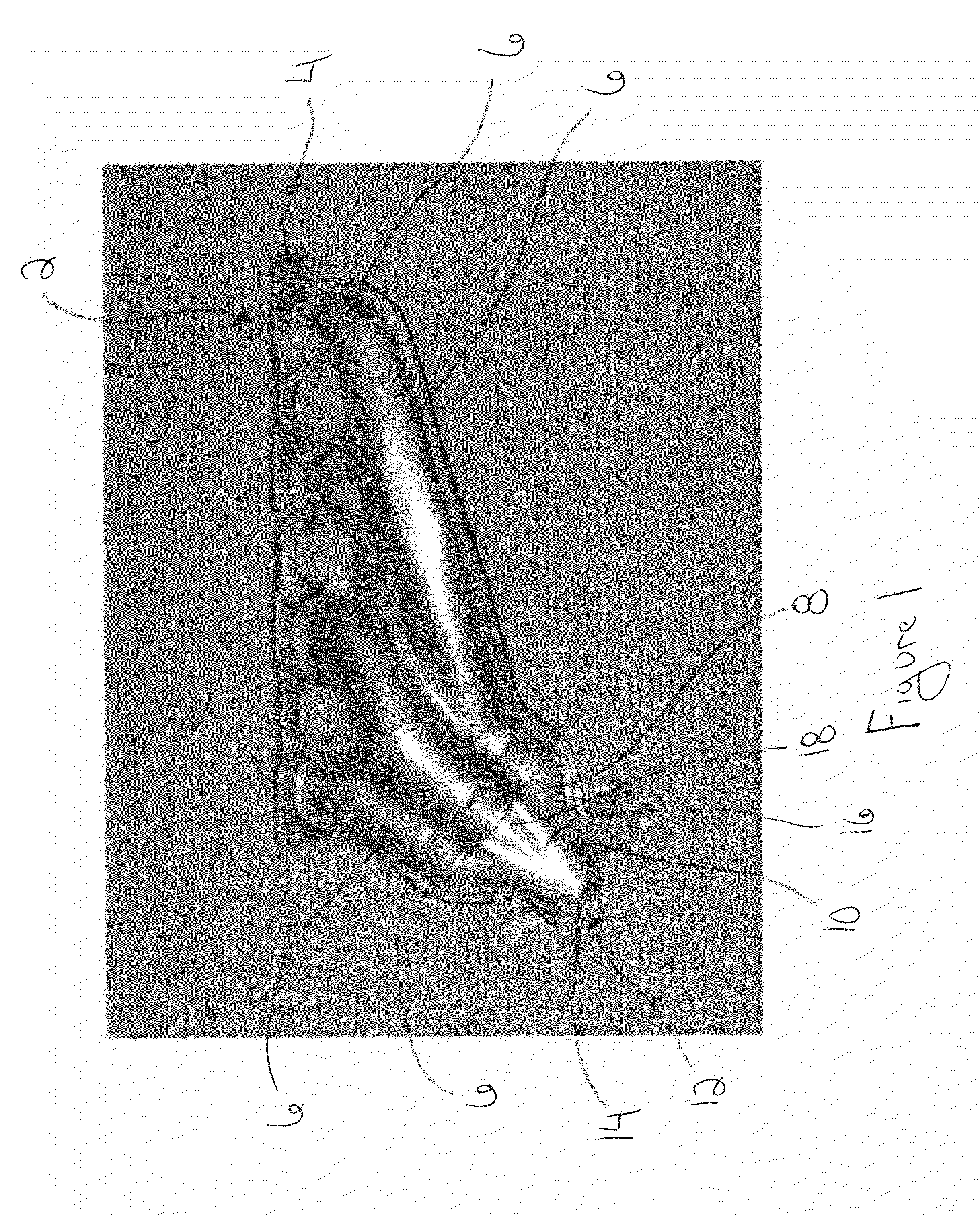
[0032]FIG. 1 is a perspective view of an original manufacturer exhaust system 2. As shown in FIG. 1, the exhaust system 2 includes a flange 4, conduits 6 and a collector 8. The flange 4 is formed to the dimensions and shape of the engine (not shown in the Figures) to which it is to be attached. As shown in FIG. 1, the flange 4 may be coupled to the engine with mechanical fasteners, such as bolts. The conduits 6 extend from the flange 4 to the collector 8. The conduits 6 may be of varying length depending on the space available in the engine compartment. The flange 4 has openings therein to allow exhaust gas from an engine's cylinders to pas...


PUM


Abstract

A system and method for increasing the performance of an internal combustion engine having a stock exhaust manifold. An exhaust insert affixed to or positioned downstream from the cylinder exhaust ports, in the exhaust conduits, in the stock manifold, in the collector, before or after the catalytic converter, before or after any Y-pipe, or any location in the exhaust system. The exhaust insert having a pre-determined size and shape to optimize performance, including, but not limited to, fuel efficiency, emissions, and power.

Description

TECHNICAL FIELD[0001]Exemplary embodiments of the invention relate to exhaust system inserts from internal combustion engines (e.g., gasoline, diesel, biodiesel, compressed natural gas, alcohol, ethanol, and other similar combustion engines). More particularly, exemplary embodiments relate to the placement of an insert into an original manufacturers exhaust system of an internal combustion engine in order to improve engine performance, including, but not limited to, fuel efficiency, emissions control, and power.BACKGROUND[0002]The performance and efficiency of internal combustion engines depends on the efficient movement of gases through the engine, from the introduction of air and fuel through the intake ports into the cylinders of the engine to exhaust of the combustion by-products through the exhaust ports. The exhaust system performs a critical role in this process and has a significant impact on efficiency of the engine. The exhaust system operates to provide complete and effic...

Claims


Application Information

Patent Timeline
IPC IPC(8): F01N3/00
CPCF01N3/00F01N13/08F01N13/10F02B27/04F01N2260/14Y02T10/12
Inventor BELANGER, LOUIS A.
Owner EGM TECH
Why Eureka
Try Eureka