Multistaged Lean Prevaporizing Premixing Fuel Injector

a fuel injector and prevaporization technology, applied in the direction of machines/engines, transportation and packaging, lighting and heating apparatus, etc., can solve the problems of inability to sustain combustion processes at these extremely lean operating conditions, more problems in the lean prevaporization premixed injector system coupled with fuel composition changes, and inability to complete combustion and the attendant emissions, etc., to achieve the effect of low emissions

Active Publication Date: 2013-11-21
CAPSTONE TURBINE
View PDF11 Cites 35 Cited by
  • Summary
  • Abstract
  • Description
  • Claims
  • Application Information

AI Technical Summary

Benefits of technology

[0010]A multistaged lean prevaporizing premixing dual fuel injector is provided, particularly for use in a low emission combustion system of a microturbine. Particularly when using such injectors with liquid fuel, the fuel and air preparation process to finely atomize, fully vaporize the liquid fuel and then fully mix the fuel with combustion air prior to the onset of the combustion process is important to achieve low emissions, especially for NOx levels below 9 ppmv (parts per million by volume) (at 15% O2) emission levels.
[0011]A multistaged lean prevaporizing premixed dual fuel injector is disclosed which can be used to burn liquid fuel and more than one gaseous fuel at the same time. High temperature air is used to provide energy for vaporizing the atomized liquid fuel droplets. In an embodiment, the high temperature may be provided from the same source as the combustion air for the microturbine, which is the heated incoming air from the recuperator. The air temperature for the preheated combustion air coming from the recuperator may be in the range of from about 900° F. to about 1300° F. The use of preheated combustion air from the recuperator as the vaporizing air for the fuel injector greatly reduces system complexity and improves system reliability.

Problems solved by technology

Very lean ignition and combustion, however, inevitably result in incomplete combustion and the attendant emissions which result therefrom.
In addition, combustion processes cannot be sustained at these extremely lean operating conditions.
Lean prevaporized premixed injector systems coupled with fuel composition changes are more subject to problems such as combustion instability, flashback and auto ignition.

Method used


Image

  • Multistaged Lean Prevaporizing Premixing Fuel Injector
  • Multistaged Lean Prevaporizing Premixing Fuel Injector
  • Multistaged Lean Prevaporizing Premixing Fuel Injector

Examples


Embodiment Construction

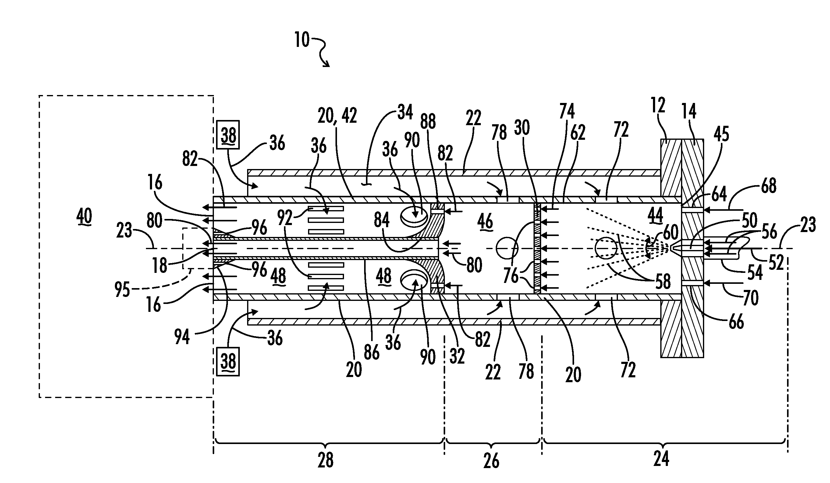
[0026]Referring now to FIG. 1 a fuel injector is shown and generally designated by the numeral 10. The fuel injector 10 is shown somewhat schematically in FIG. 1. Although the general geometry of the injector 10 may vary, in one embodiment the injector 10 is a modularized tubular design with mounting flanges 12 and 14 on one end, and outlets 16 and 18 on the other end. In between is the injector body which includes inner and outer concentric tubes 20 and 22. In the embodiment illustrated the fuel injector apparatus 10 has a central longitudinal axis 23.

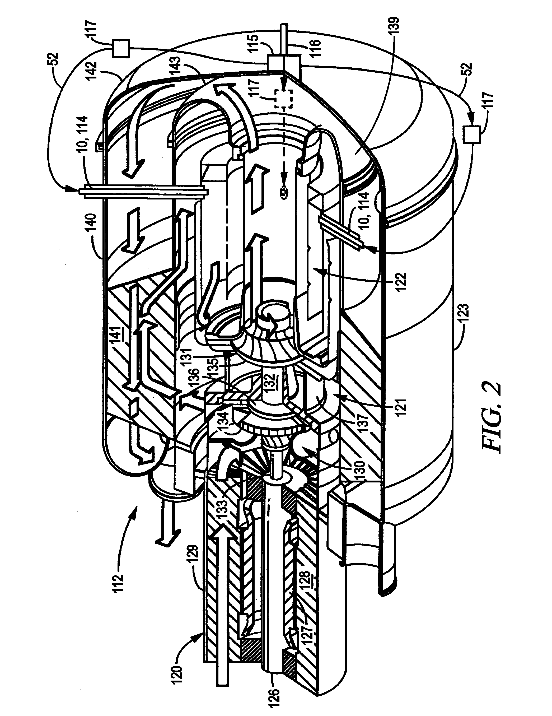
[0027]As is further explained below with regard to the embodiment of FIG. 6, the outer tube 22 may be an angled injector mounting tube 158 extending through the annular recuperator 123 of a turbogenerator, and the flange 12 may be a mounting boss 156 located on an outer recuperator wall 157. The inner tube 20 in turn may be a fuel injector tube 161 and the flange 14 may be an angled fuel injector flange 155 complementary to the mounti...


PUM


Abstract

A multistaged lean prevaporizing premixing fuel injector apparatus is provided. The fuel injector may be utilized with a turbogenerator. Preheated combustion air from the turbogenerator's recuperator may be utilized by the fuel injector to prevaporize liquid fuel. The injector may provide for premixing of multiple fuel streams and include multiple stages with a flow distributor plate separating adjacent stages. The injector may include multiple stages, with a pilot tube located in a final stage splitting the fuel stream into a premixed pilot stream and a premixed final fuel and air mixture stream.

Description

BACKGROUND OF THE INVENTION[0001]1. Field of the Invention[0002]The present invention relates generally to the field of multistaged lean prevaporizing premixing fuel injectors, and more particularly to an improved low emissions combustion system for a gas turbine engine using such injectors.[0003]2. Description of the Prior Art[0004]In a gas turbine engine, inlet air is continuously compressed, mixed with fuel in an inflammable proportion, and then contacted with an ignition source to ignite the mixture which will then continue to burn. The heat energy thus released then flows in the combustion gases to a turbine where it is converted to rotary energy for driving equipment such as an electrical generator. The combustion gases are then exhausted to atmosphere after giving up some of their remaining heat in a recuperator to the incoming air provided from the compressor.[0005]Quantities of air greatly in excess of stoichiometric amounts are normally compressed and utilized to keep the ...

Claims


Application Information

Patent Timeline
Patent Type & Authority Applications(United States)
IPC IPC(8): B01F5/04
CPCF23D11/402F23D11/408F23D11/441F23D17/002F23L15/04F23R3/286F23R3/32F23R3/36Y02E20/34Y10T137/87587F02C3/22F02C3/24F23R3/343
Inventor MITCHELL, MARK G.CHEN, JUNHUA
Owner CAPSTONE TURBINE
Why Eureka
Try Eureka