Strip heatsink

a heatsink and strip technology, applied in semiconductor devices, lighting and heating apparatus, semiconductor devices, etc., can solve the problems of insufficient heat conduction, insufficient surface area, and inability to dissipate heat of electronic components inside the computer, so as to improve the efficiency of conduction and convection, and increase the heat dissipation

Inactive Publication Date: 2013-11-21
TUNG CHIA MING
View PDF10 Cites 12 Cited by
  • Summary
  • Abstract
  • Description
  • Claims
  • Application Information

AI Technical Summary

Benefits of technology

[0010]The main objective of the present invention is to provide a strip heatsink that can increase the heat dissipation by enhancing the efficiency of conduction and convection.
[0011]The strip heatsink in accordance with the present invention has a base, multiple dissipating strips and a fastening loop. The strip heatsink uses a row of the dissipating strips to replace one conventional fin, and a shape of the strip part of each dissipating strip is circular. Therefore a whole surface area of the row of the dissipating strips is much bigger. Besides, because a cross section area of the mounting part is bigger than a cross section area of the strip part in a dissipating strip, the strip parts of the dissipating strips are mounted separately, and the blocking of the airflow is reduced. Therefore, air can flow more smoothly in an interval between the strip parts. To sum up, the strip heats ink enhances the heat conduction by increasing the whole surface area, and enhances the heat convection by making more space between the dissipating strips.

Problems solved by technology

However, to dissipate heat of the electronic components inside the computer is always a difficult problem, especially as the lifespan and the working stability of the electronic components depend on the working temperature.
Therefore, the whole surface area is not large enough, and the heat conduction is not good enough.
The fresh air is hard to move in, and the hot air is hard to move out.
Then the heatsink has poor heat convection.

Method used


Image

  • Strip heatsink
  • Strip heatsink
  • Strip heatsink

Examples


first embodiment

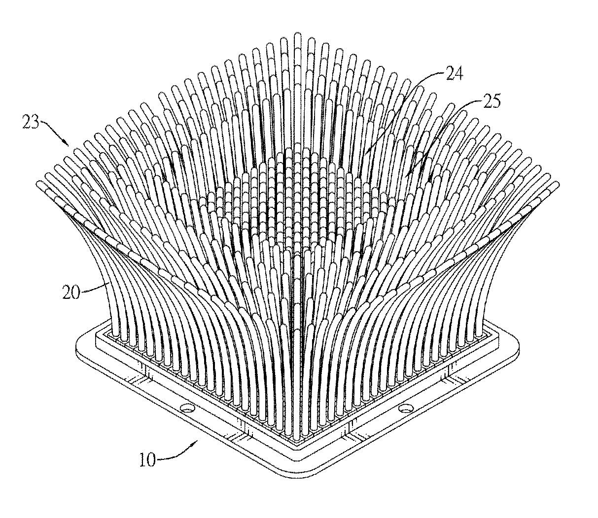
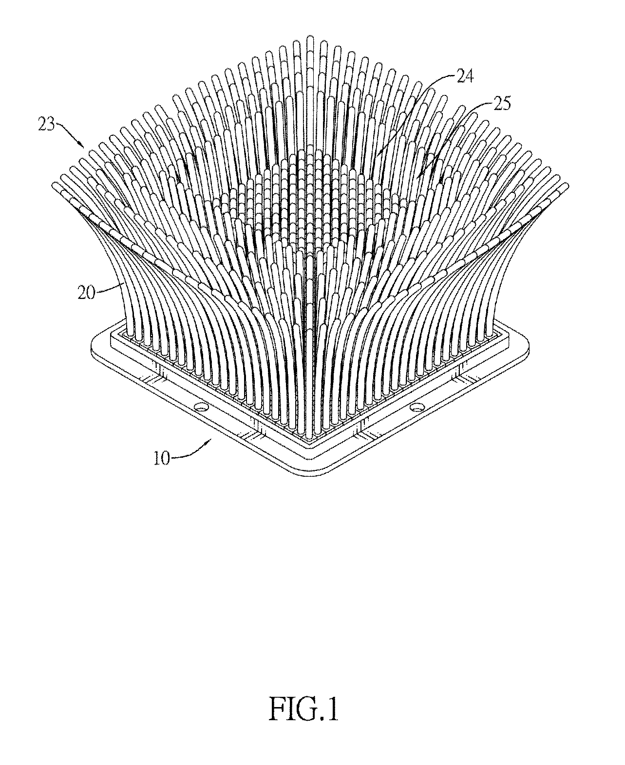
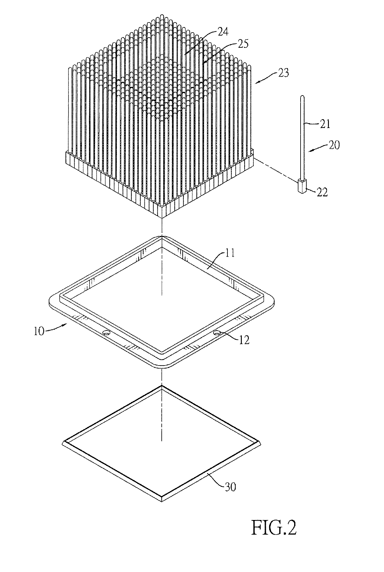
[0019]With reference to FIGS. 1 and 2, a strip heatsink in accordance with the present invention comprises a base 10, a periphery dissipating assembly 23, a central dissipating assembly 24 and a fastening loop 30.

[0020]With reference to FIGS. 2 to 4, the base 10 has a mounting hole 11 formed through the base 10. In a preferred embodiment, the mounting hole 11 is rectangular. Besides, the base 10 has multiple connecting holes 12. The connecting holes 12 are formed through the base 10 and are arranged surrounding the mounting hole 11.

[0021]With reference to FIGS. 1 and 3, the central dissipating assembly 24 is surrounded by the periphery dissipating assembly 23. Each dissipating assembly 23, 24 comprises multiple dissipating strips 20. The dissipating strips 20 are mounted securely in the mounting hole 11 of the base 10. Each dissipating strip 20 has a strip part 21 and a mounting part 22. The strip part 21 has a top end. The mounting part 22 is formed on a bottom of the strip part 21...

second embodiment

[0027]The mounting part 22 of the dissipating strips 20 may be formed in different shapes. In a second embodiment as shown in FIGS. 5 and 6, the cross section of the mounting part 22A of each dissipating strip 20A is hexagonal, thereby also making the dissipating strip 20A arranged in order and forming the interval between the strip parts 21 A of the dissipating strip 20A.


PUM


Abstract

A strip heatsink has a base, multiple dissipating strips and a fastening loop. The strip heatsink uses a row of the dissipating strips to replace one conventional fin, and a shape of the strip part of each dissipating strip is circular. Therefore a whole surface area of the row of the dissipating strips is much bigger. Besides, because a cross section area of the mounting part is bigger than a cross section area of the strip part in a dissipating strip, the strip parts of the dissipating strips are mounted separately, and the blocking of the airflow is reduced. Therefore, air can flow more smoothly in an interval between the strip parts. To sum up, the strip heatsink enhances the heat conduction by increasing the whole surface area, and enhances the heat convection by making more space between the dissipating strips.

Description

BACKGROUND OF THE INVENTION[0001]1. Field of the Invention[0002]The present invention relates to a strip heatsink, especially to a strip heatsink that increases the heat dissipation by enhancing the efficiency of conduction and convection.[0003]2. Description of the Prior Arts[0004]With the development of technology, the computers compute faster with increasing capabilities. However, to dissipate heat of the electronic components inside the computer is always a difficult problem, especially as the lifespan and the working stability of the electronic components depend on the working temperature. As a result, the electronic components must be kept at a reasonable temperature by the heatsink to dissipate heat.[0005]The conventional heatsink comprises a base and multiple fins. The base is attached tightly to the electronic component, such as the central processing unit (CPU). The heat is conducted from the CPU through the base and fins to the air around the fins by heat conduction. Then...

Claims


Application Information

Patent Timeline
Patent Type & Authority Applications(United States)
IPC IPC(8): F28F7/00
CPCH01L23/3677H01L2924/0002H01L2924/00
Inventor TUNG, CHIA-MING
Owner TUNG CHIA MING
Why Eureka
Try Eureka