
Miniaturized uhf RFID tag for implantable medical device

Active Publication Date: 2013-11-21
WARSAW ORTHOPEDIC INC
View PDF2 Cites 9 Cited by
  • Summary
  • Abstract
  • Description
  • Claims
  • Application Information

AI Technical Summary

Benefits of technology

The patent text describes a RFID tag design that minimizes interference with metallic materials, has high performance, is robust against environmental stresses, and optimizes the performance of RLC components. Additionally, the RFID tag has a low detuning effect that reduces interference with other RFID tags.

Problems solved by technology

Conventional RFID inventory management systems fail to provide fast and error-proof information in a timely manner, which creates inefficiencies.

Method used


Image

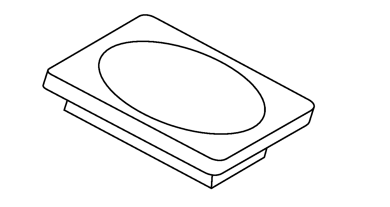
  • Miniaturized uhf RFID tag for implantable medical device
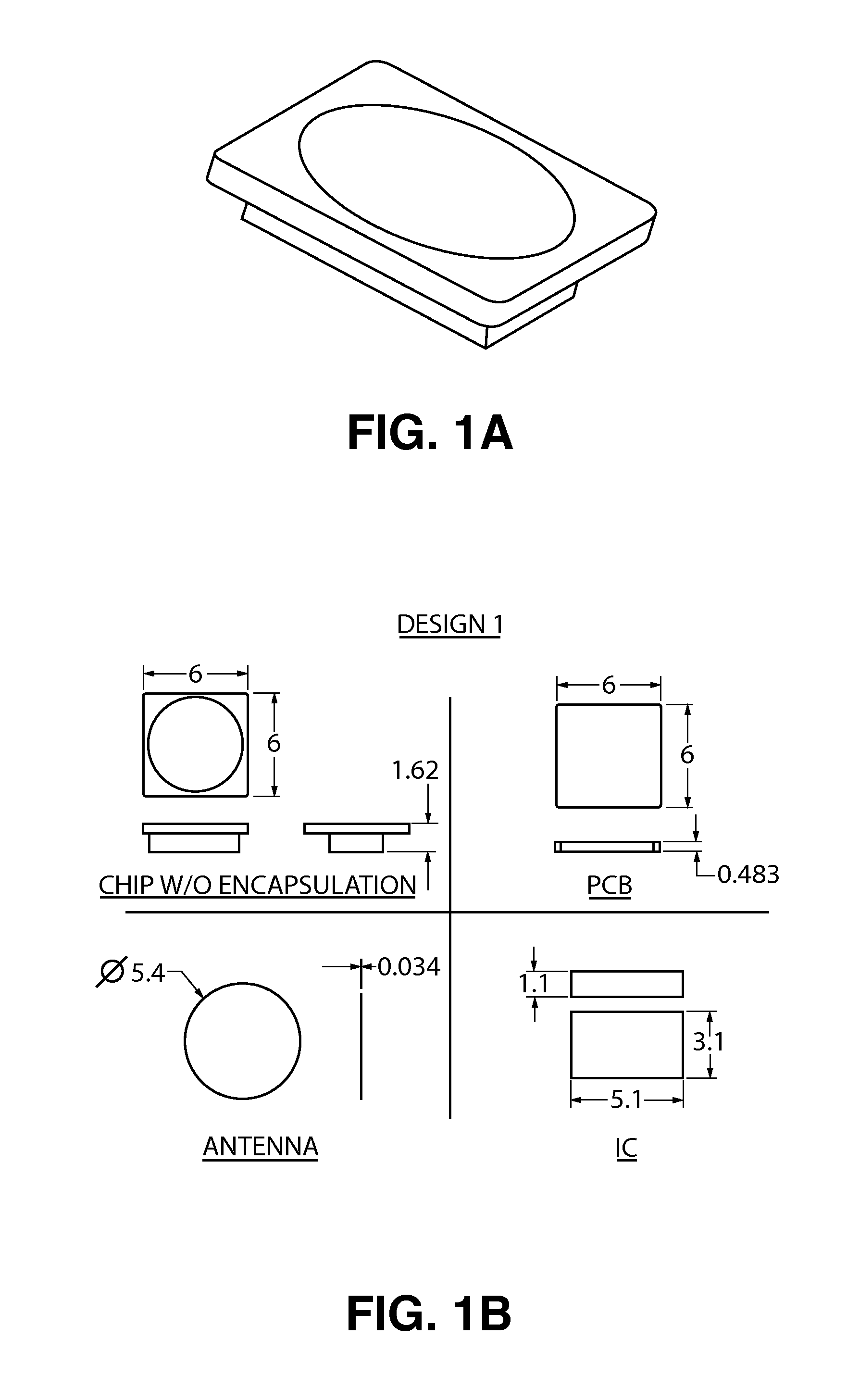
  • Miniaturized uhf RFID tag for implantable medical device
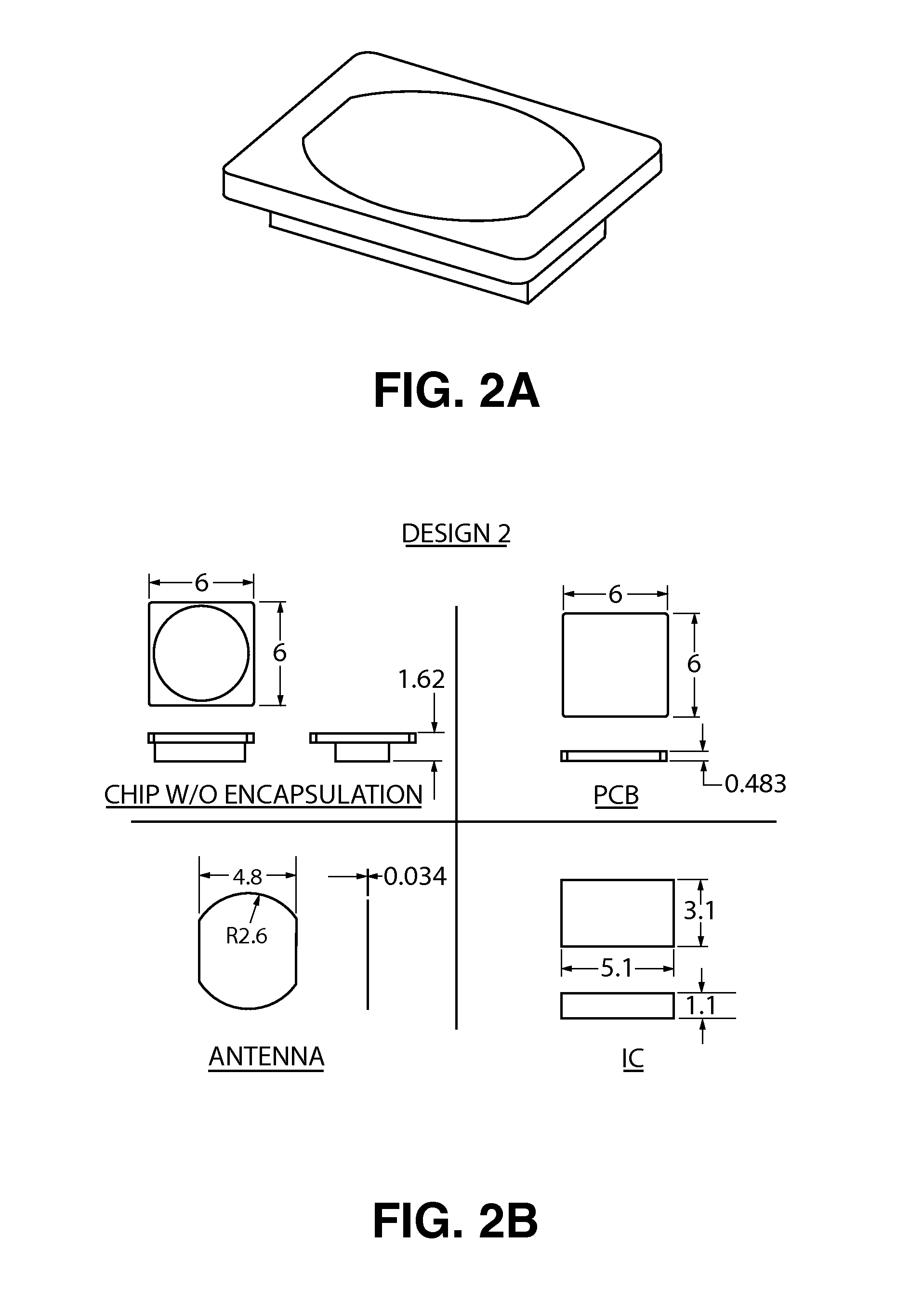
  • Miniaturized uhf RFID tag for implantable medical device

Examples


Embodiment Construction

[0037]In the following detailed description, reference is made to the accompanying drawings that form a part hereof, and in which are shown by way of illustration several embodiments of devices, systems and methods. It is to be understood that other embodiments are contemplated and may be made without departing from the scope or spirit of the present disclosure. The following detailed description, therefore, is not to be taken in a limiting sense.

[0038]All scientific and technical terms used herein have meanings commonly used in the art unless otherwise specified. The definitions provided herein are to facilitate understanding of certain terms used frequently herein and are not meant to limit the scope of the present disclosure.

[0039]As used in this specification and the appended claims, the singular forms “a”, “an”, and “the” encompass embodiments having plural referents, unless the content clearly dictates otherwise.

[0040]As used in this specification and the appended claims, the ...


PUM


Abstract

This invention relates to a novel architecture of a passive RFID (Radio-Frequency Identification) tag which is highly miniature in size, capable of metal mounting and suitable for global operation in the entire UHF band (860 MHz to 960 MHz) without necessity of territory specific optimization of the antenna design layout.This invention envisages a novel antenna design that consists of a circular or rectangular microstrip antenna of ultra-small size (−λ / 50), which is suitably loaded in shunt by lumped components resistor (R), inductor (L) and capacitor (C). The feed point, feed layout and the loading values are so optimized that a single tag will display optimum performance in all the territories.This invention relates to a method of encapsulating the passive tag with radio transparent materials like Radel® R, as well as a metal backplane so that the encapsulated tag can withstand autoclaving while maintaining the required performance.

Description

FIELD OF THE INVENTION[0001]The present invention relates to radio frequency identification (RFID) tags that are particularly suitable for item location, identification, inventory and tracking applications in the medical device industry.BACKGROUND OF THE INVENTION[0002]An RFID system consists of a reader (sometimes called an interrogator) and a transponder (or tag), which usually has a microchip with an attached antenna. There are different types of RFID systems, but usually the reader sends out electromagnetic waves that the tag is designed to receive. Passive tags have no power source. Passive tags draw power from the field created by the reader and use the energy from the field to power the microchip's circuits. The chip then modulates the waves that the tag sends back to the reader. The reader then converts the new waves into digital data. Active tags have a power source and broadcast their signal. Active real time location systems don't respond to signals from the reader, but r...

Claims


Application Information

Patent Timeline
IPC IPC(8): G06K19/077
CPCA61F2250/0002G06K19/02G06K19/07749H01L23/66H01L2223/6627H01L2223/6655H01L2223/6677H01L2924/0002H01Q1/2225H01Q9/0407H01L2924/00
Inventor MATHEWS, MICHAELTAPAS, CHAKRAVARTYTETHRAKE, STEVENTURNER, ROBINTYAGI, KULDEEP
Owner WARSAW ORTHOPEDIC INC
Learn More