Power factor correction circuit

a power factor and circuit technology, applied in the direction of electric variable regulation, process and machine control, instruments, etc., can solve the problems of overshooting of output voltage, steep intermittent oscillating operation of repeatedly oscillating and stopping oscillating, etc., to suppress an increase of output voltage, reduce the level of switching current, and reduce the effect of switching current comparatively easily

Active Publication Date: 2013-11-21
SHINDENGEN ELECTRIC MFG CO LTD
View PDF18 Cites 5 Cited by
  • Summary
  • Abstract
  • Description
  • Claims
  • Application Information

AI Technical Summary

Benefits of technology

[0023]According to the invention of the claim 1, the output voltage control circuit performs constant voltage-control such that the capacitor charge voltage of the output capacitor corresponds to the first voltage value, and when the capacitor charge voltage of the output capacitor reaches the second voltage value higher than the first voltage value, the overvoltage detecting unit detects the second voltage value. Further, the current limiting unit detects the value of the switching current through the switching element, the limiting value of the level of the switching current is determined along with this, and the value of the switching current is limited to the limiting value. Then, when the overvoltage detecting unit detects the second voltage value, the limiting value changing unit causes the current limiting unit to change the limiting value so as to decrease the level of the switching current. Accordingly, an effect is provided that even under a condition that the output voltage of the booster-type switch-mode power supply is susceptible to overshoot, it is possible to decrease the switching current comparatively easily when the output voltage is in an overshoot state. As a result, an effect is provided that it is possible to suppress an increase of the output voltage, and to prevent generation of ringing sound in a transformer. In addition, an effect is provided that as a complicated control circuit is not required, it is possible to provide a booster-type switch-mode power supply capable of satisfying reduction of both of a size and a cost of the devices.
[0024]According to the invention of the claim 2, even under the condition that the output voltage of the booster-type switch-mode power supply is susceptible to overshoot, it is possible to further decrease the switching current comparatively easily when the output voltage is in the overshoot state. As a result, an effect is provided that it is possible to further suppress the output voltage, and to further prevent generation of ringing sound in the transformer. In particular, when a self-excited power source is used, there is a case in which an intermittent oscillation operation in an audible frequency band occurs under a condition of a light load. However, as the value of the switching current is decreased even lower than that in the case in which the overvoltage detecting unit detects the second voltage value, an effect is provided that it is also possible in this case to reduce the generation of ringing sound in the transformer. It should be noted that while there is a case in which a continuous oscillation occurs instead of an intermittent operation under the condition of a light load when a self-excited power source is used, it should be understood that the effect is also provided that it is possible in this case to reduce the generation of ringing sound in the transformer.
[0025]According to the invention of the claim 3, the current limiting unit is constituted by a comparator having: the negative terminal connected to the reference power source corresponding to the first voltage value; the output connected to the oscillation control unit configured to control oscillation of the switching element; and the positive terminal supplied with the signal obtained by superimposing the current level signal corresponding to the value of the switching current and the limiting value changing signal outputted from the limiting value changing unit for causing the current limiting unit to change the limiting value. Therefore, an effect is provided that it is possible to change the limiting value by changing a threshold value equivalently with a simple mode of connecting an output signal from the limiting value changing unit to the positive terminal of an overcurrent detecting circuit configured by a common comparator.
[0026]According to the invention of the claim 4, an effect is provided that the overvoltage detecting unit detects the third voltage value when the capacitor charge voltage of the output capacitor reaches the third voltage value higher than the second voltage value, and controls the oscillation control unit to discontinue and hold the switching of the switching element. Thus, even when the output voltage is in the overshoot state and increases up to the third voltage value, it is possible to stop the power factor correction circuit reliably and easily.
[0027]According to the invention of the claim 5, the control circuit is configured such that the limiting value change end signal indicating that the change of the limiting value has ended is transmitted to the load side at the timing when the state in which the limiting value changing unit causes the current limiting unit to change the limiting value resumes to the state before the change. Accordingly, as the information that the current limiting level of the switching current is limited to the limiting value is transmitted to the load side, an effect is provided that when another electric circuit is connected to the output of the power factor correction circuit according to the present invention, for example, it is possible to prohibit the operation of this electric circuit even when the output voltage of the power factor correction circuit is not stably constant voltage-controlled at the first voltage value by controlling an operation of the electric circuit based on the limiting value change end information.

Problems solved by technology

Accordingly, as a feedback control is typically performed in a booster-type switch-mode power supply so as not to respond to a commercial frequency, an output response to a sudden change of an input and a sudden change of a load may easily delay, and thus overshoot of an output voltage may easily produced.
However, according to the conventional technique described in Patent Literature 1, as illustrated in FIG. 10 (FIG. 11 is a timing chart showing a timing chart in FIG. 9 in a wider timeline), in activation when the commercial alternating-current source is applied to the input of the direct-current source circuit, it is probable that an output voltage steeply increases and an intermittent oscillating operation of repeatedly oscillating and stopping oscillating may occur.

Method used


Image

  • Power factor correction circuit
  • Power factor correction circuit
  • Power factor correction circuit

Examples


first embodiment

[0047]The first embodiment of the present invention will be described with reference to FIG. 2 through FIG. 5. It should be noted that according to this embodiment, when an output voltage exceeds a second voltage value, a switching current is suppressed to a current value lower than that in OCP (overcurrent detection).

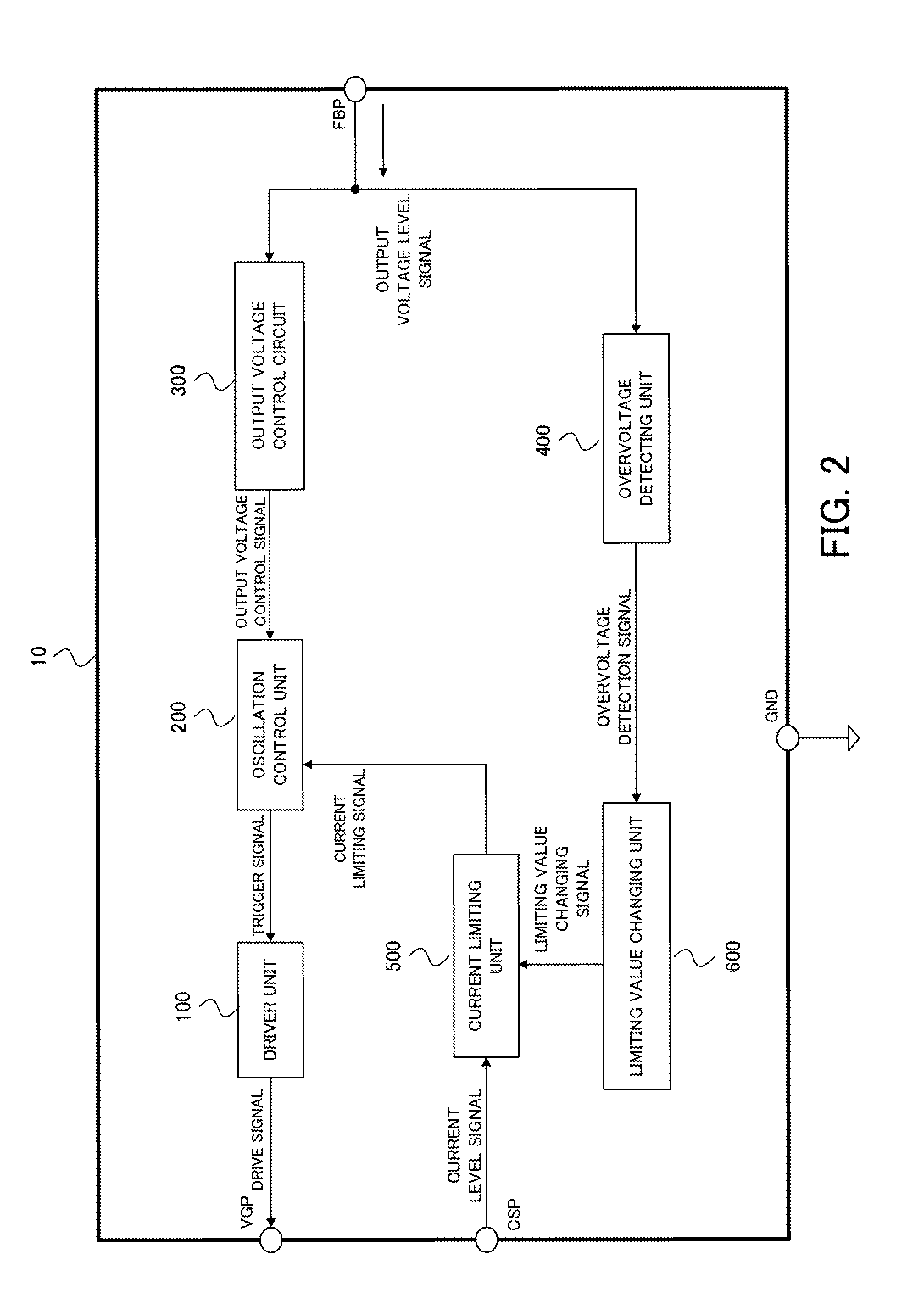
[0048]Configurational blocks of the control circuit according to this embodiment will be described with reference to FIG. 2.

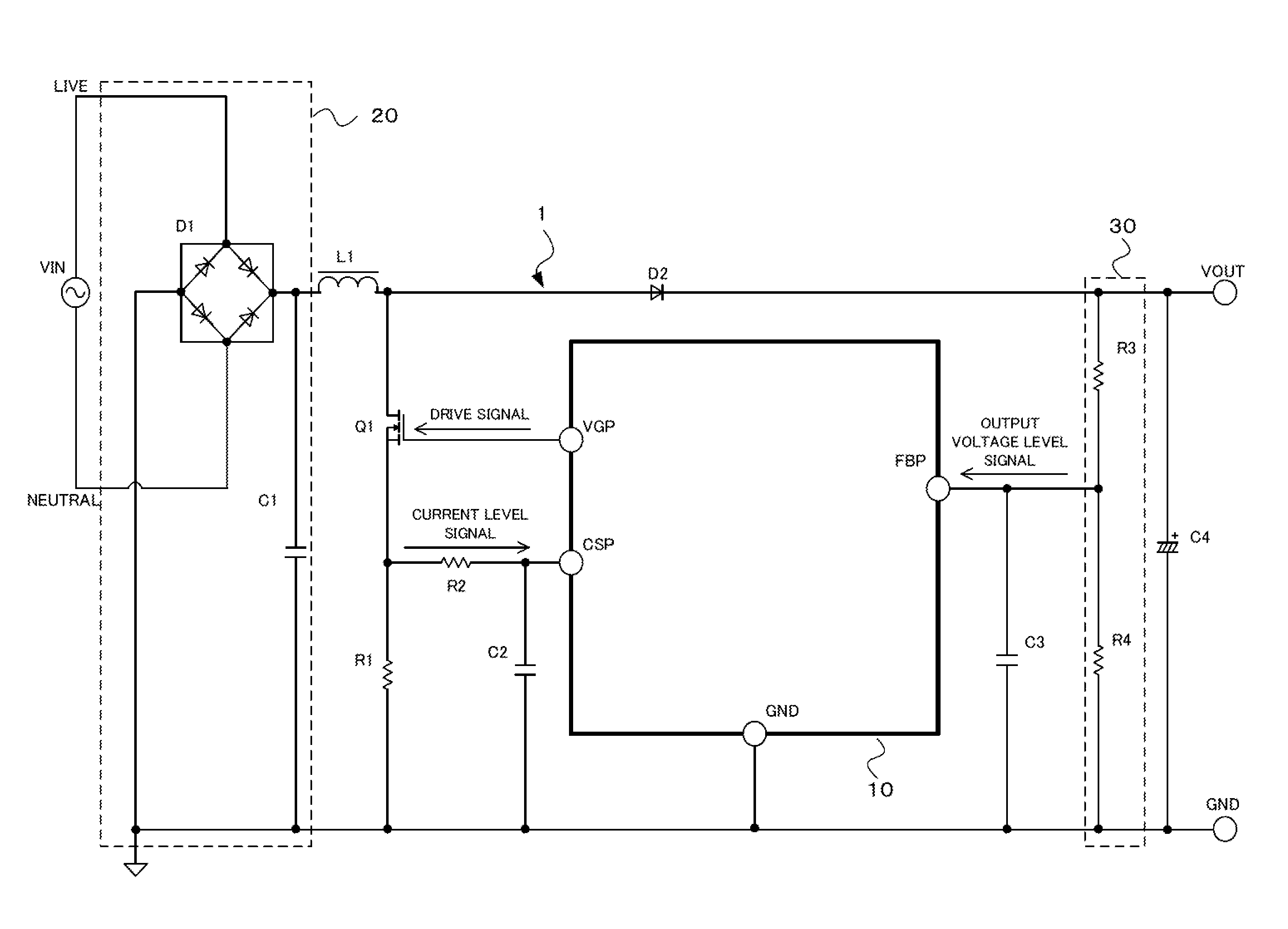
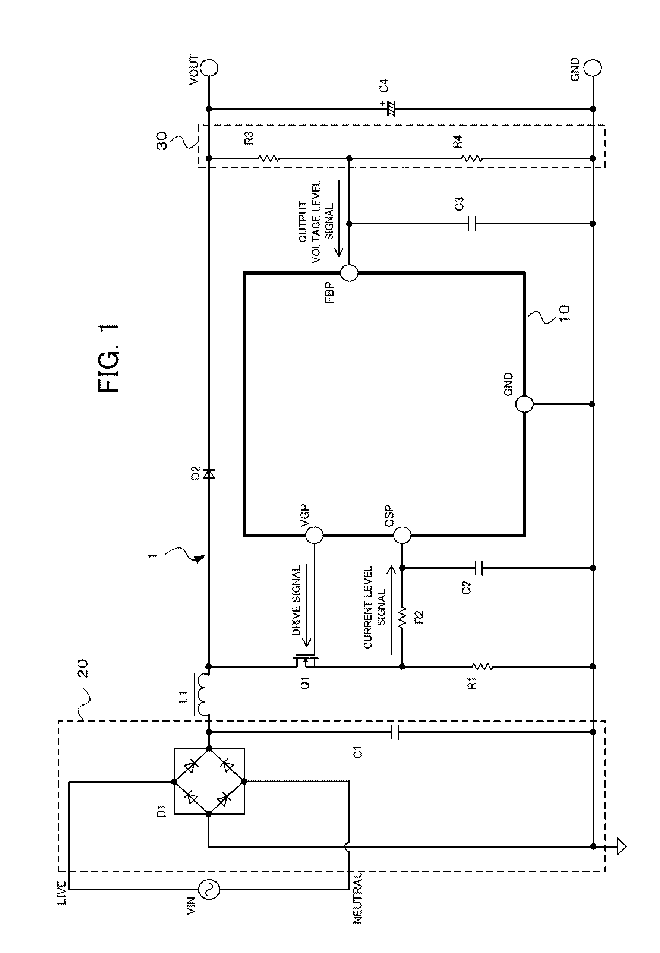
[0049]Referring to FIG. 2, the control circuit 10 according to this embodiment is provided with a driver unit 100, an oscillation control unit 200, an output voltage control circuit 300, an overvoltage detecting unit 400, a current limiting unit 500, and a limiting value changing unit 600.

[0050]Here, the output voltage control circuit 300 performs constant voltage-control such that the value of the output voltage corresponds to a first voltage value by inputting an output voltage level signal corresponding to a capacitor charge voltage of the outp...

second embodiment

[0066]The second embodiment of the present invention will be described with reference to FIG. 6 and FIG. 7. It should be noted that according to this embodiment, when the overvoltage detecting unit detects the third voltage value that is higher than the second voltage value, the switching of the switching element is controlled to be discontinued and held.

[0067]Configurational blocks of the control circuit according to this embodiment will be described with reference to FIG. 6.

[0068]Referring to FIG. 6, the control circuit 10 according to this embodiment is provided with the driver unit 100, an oscillation control unit 210, the output voltage control circuit 300, an overvoltage detecting unit 410, the current limiting unit 500, and the limiting value changing unit 600. It should be noted that components denoted by the same reference numerals as those in the first embodiment have the same functions as those in the first embodiment, and therefore detailed descriptions for such componen...

third embodiment

[0075]The third embodiment of the present invention will be described with reference to FIG. 5 and FIG. 8. It should be noted that according to this embodiment, a limiting value change end signal indicating that the change of the limiting value has ended is transmitted to a load side at timing when the state in which the limiting value changing unit causes the current limiting unit to change the limiting value resumes to a state before the change.

[0076]Configurational blocks of the control circuit according to this embodiment will be described with reference to FIG. 8.

[0077]Referring to FIG. 8, the control circuit 10 according to this embodiment is provided with the driver unit 100, the oscillation control unit 210, the output voltage control circuit 300, the overvoltage detecting unit 410, the current limiting unit 500, the limiting value changing unit 600, and a limiting value change end transmission unit 700. It should be noted that components denoted by the same reference numera...


PUM


Abstract

Provided is a power factor correction circuit capable of reducing ringing sound of a transformer produced when an overshoot protection is effected. An output voltage control circuit performs constant voltage-control such that capacitor charge voltage of an output capacitor corresponds to a first voltage value, and when the capacitor charge voltage of the output capacitor reaches a second voltage value higher than the first voltage value, an overvoltage detecting unit detects the second voltage value. Further, a current limiting unit detects a value of a switching current through a switching element, and determines a limiting value of the level of the switching current. Then, the switching current is limited to the limiting value, and when an overvoltage detecting unit detects the second voltage value, a limiting value changing unit causes the current limiting unit to change the limiting value to decrease the value of the switching current.

Description

TECHNICAL FIELD[0001]The present invention relates to power factor correction circuits, and in particular to a power factor correction circuit capable satisfying measures to address overshoot of an output voltage and generation of ringing sound in a boosting inductance element and such in a case such as activation, a sudden change of an input, or a sudden change of a load, as well as reduction of a size and a cost of the devices.BACKGROUND ART[0002]Conventionally, a switch-mode power supply for power factor correction rectifies an alternating input voltage using a bridge diode, and smoothes the rectified output voltage using a capacitor for a booster-type switch-mode power supply. The rectified output from the bridge diode is controlled by a choke coil for the booster-type switch-mode power supply, a switching semiconductor switch for the booster-type switch-mode power supply, a rectifier diode for the booster-type switch-mode power supply, and a power factor correction control circ...

Claims


Application Information

Patent Timeline
Patent Type & Authority Applications(United States)
IPC IPC(8): H02M7/217
CPCH02M7/217H02M1/4225Y02B70/10Y02P80/10H02M1/42G05F1/70H02M3/155H02M7/12H02M1/32
Inventor KOIWAI, HITOSHIHISADA, SHIGERU
Owner SHINDENGEN ELECTRIC MFG CO LTD
Why Eureka
Try Eureka