Pressurizer surge-line separator for integral pressurized water reactors

a separator and pressurizer technology, applied in nuclear reactors, nuclear elements, greenhouse gas reduction, etc., can solve the problems of increasing the rate of nuclear reaction and core power, reducing the extent of neutron absorption, and the traditional method of separation of pressurizer from reactor coolant loop is not possibl

Active Publication Date: 2013-11-21
WESTINGHOUSE ELECTRIC CORP
View PDF1 Cites 18 Cited by
  • Summary
  • Abstract
  • Description
  • Claims
  • Application Information

AI Technical Summary

Benefits of technology

[0011]These and other objectives are achieved by an integral nuclear reactor having a reactor pressure vessel housing, a primary coolant flow path and a pressurizer with a surge line separator separating the pressurizer from the primary coolant flow path. The surge line separator includes two or more spaced, generally horizontal plates, each having a curved periphery that is supported in an upper portion of the reactor pressure vessel with each plate substantially spanning the inside diameter of the reactor vessel. A plurality of spaced, curved, concentric baffles extend between the spaced plates with an upper one of the two spaced, generally horizontal plates attached to at least some of the baffles and a lower one of the two spaced, generally horizontal plates attached to at least others of the baffles. A first coolant passage extends through the lower one of the two spaced, generally horizontal plates in a first area generally proximate one of either a center or the periphery of the lower one of the two spaced, generally horizontal plates. A second coolant passage extends through the upper one of the two spaced, generally horizontal plates in a second area generally proximate the other of either a center or periphery of the upper one of the two spaced, generally horizontal plates. A circuitous coolant path extends between the first and second areas to provide access to the pressurizer positioned above the upper one of the two spaced, generally horizontal plates.

Problems solved by technology

Inserting a control rod further into the core causes more neutrons to be absorbed without contributing to fission in an adjacent fuel rod; and retracting the control rods reduces the extent of neutron absorption and increases the rate of the nuclear reaction and the power output of the core.
Due to the arrangement of these components within the reactor vessel in this integral, modular reactor design, the traditional method for separating the pressurizer from a reactor coolant loop is not possible.

Method used


Image

  • Pressurizer surge-line separator for integral pressurized water reactors
  • Pressurizer surge-line separator for integral pressurized water reactors
  • Pressurizer surge-line separator for integral pressurized water reactors

Examples


Embodiment Construction

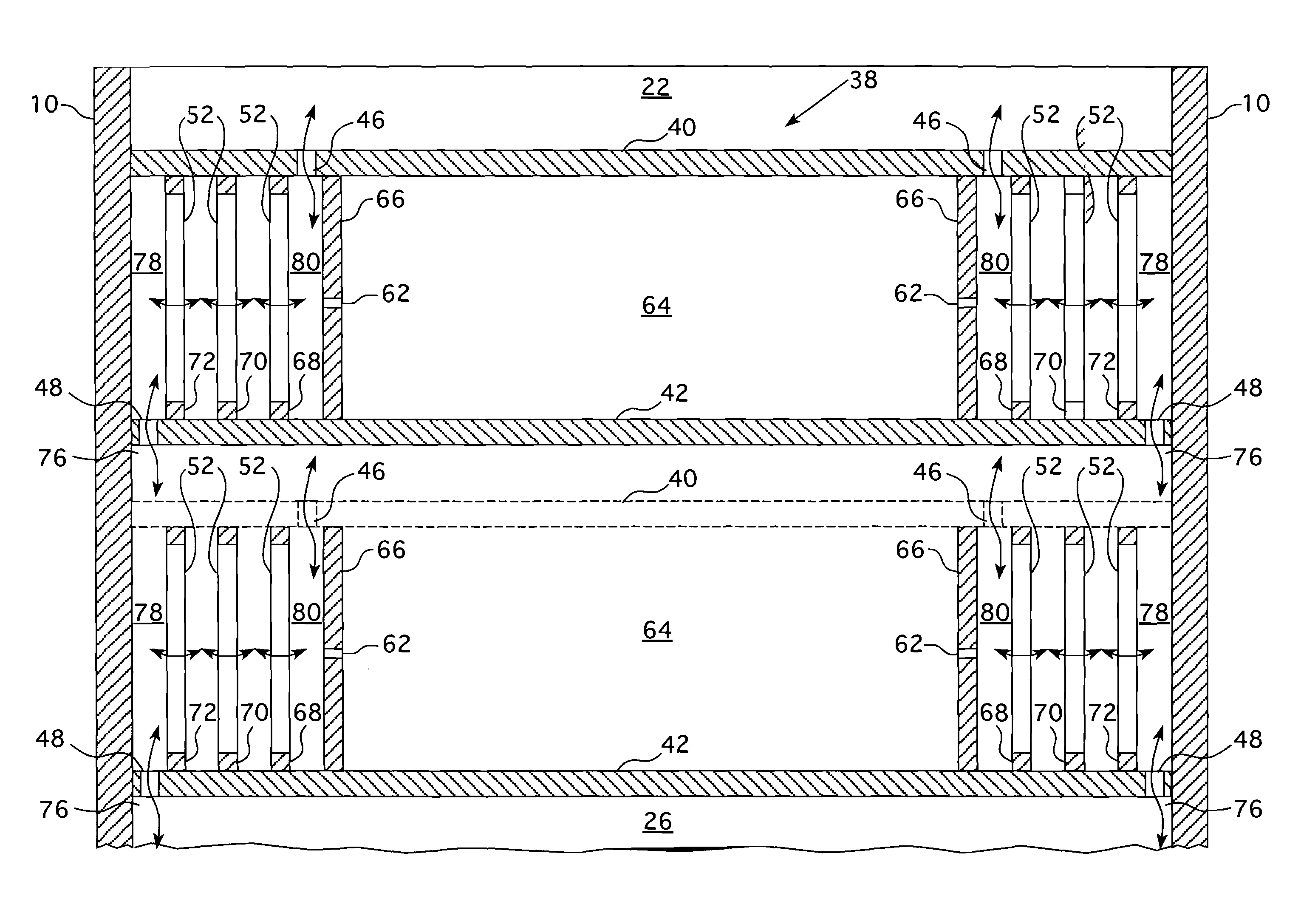
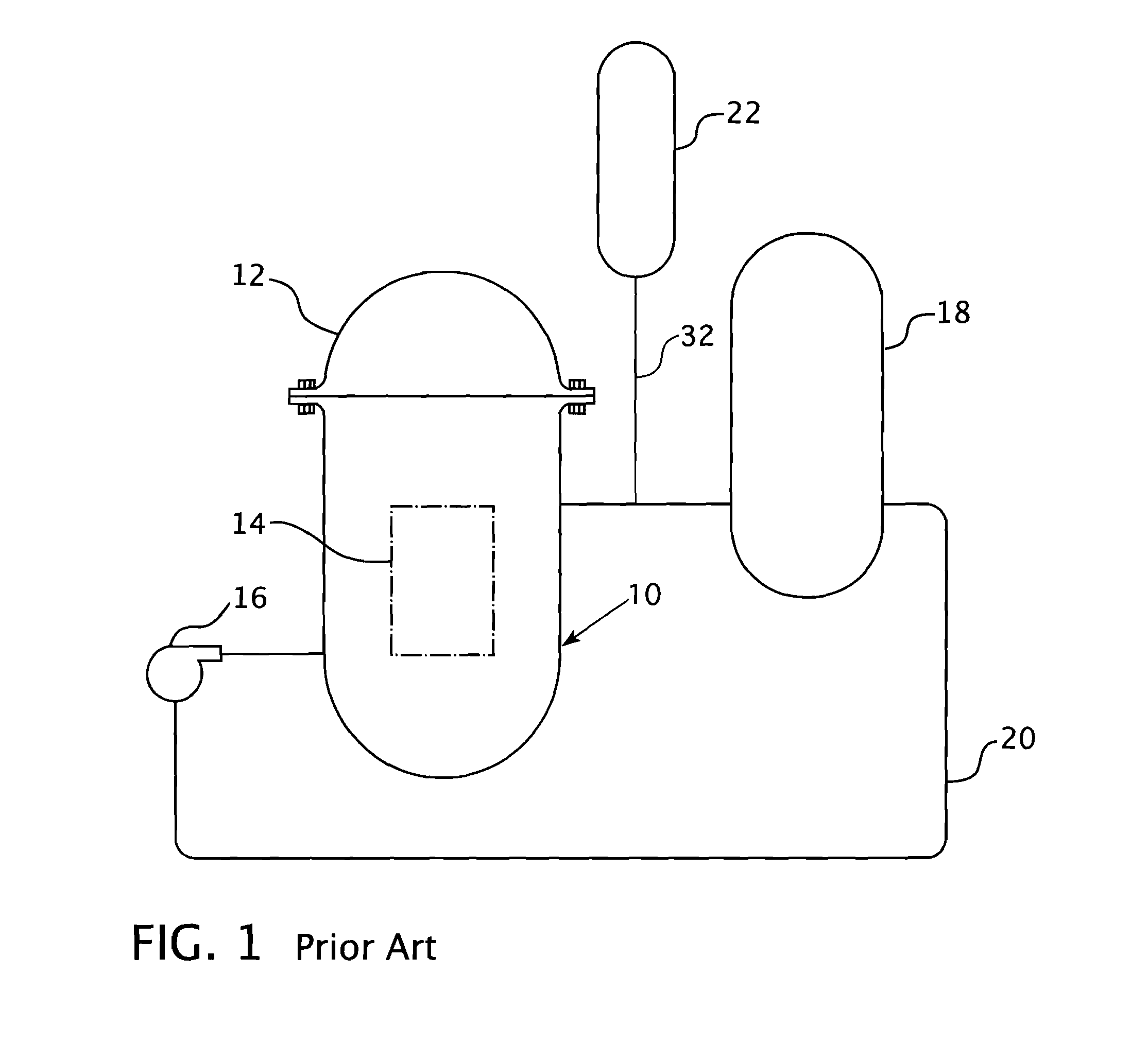
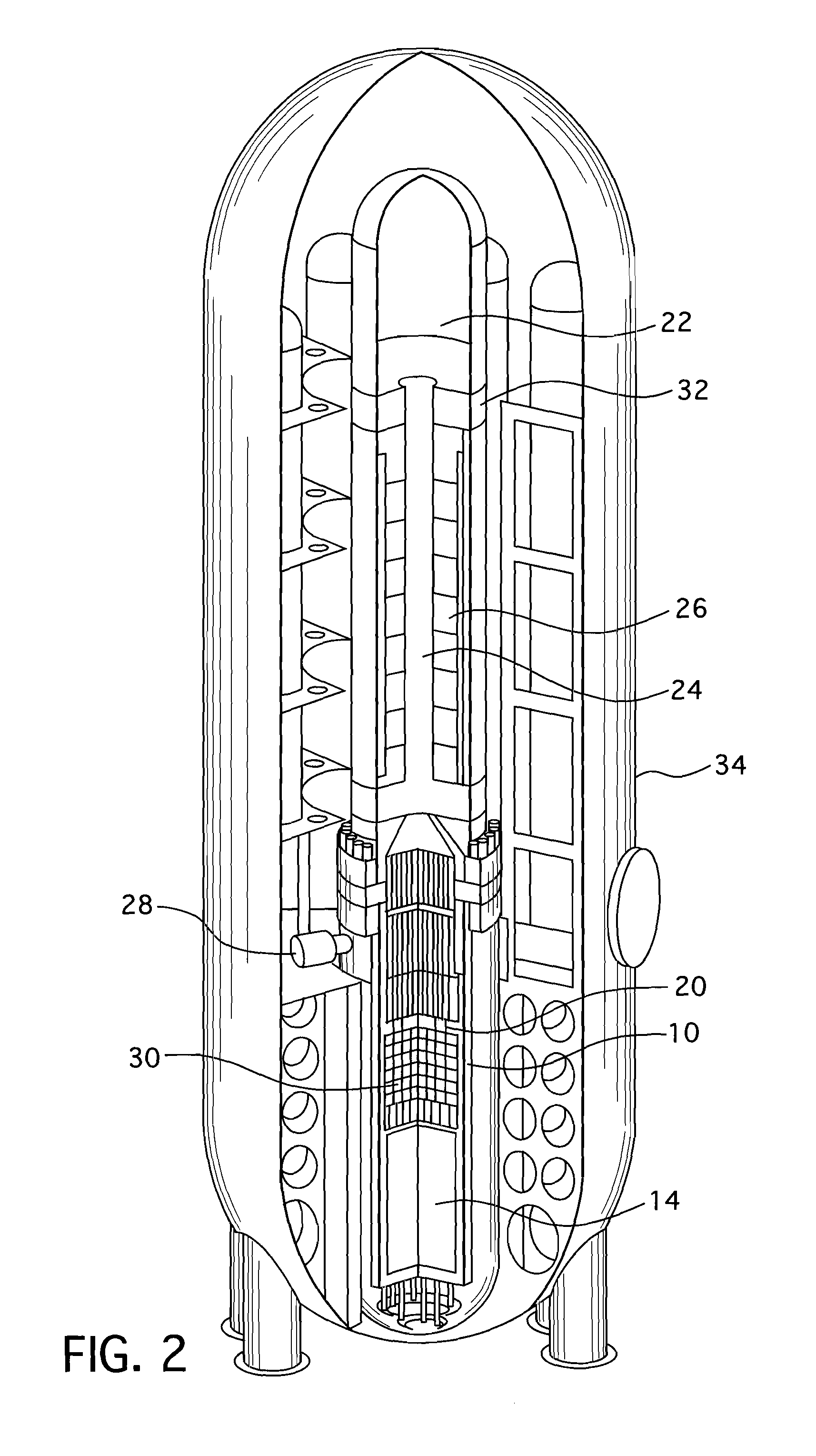
[0028]FIGS. 2 and 3 illustrate a small modular reactor design which can benefit from the surge separator design claimed hereafter. FIG. 2 shows a perspective view, partially cut away, to show the pressure vessel and its integral, internal components. FIG. 3 is an enlarged view of the pressure vessel shown in FIG. 2. Like reference characters are used among the several figures to identify corresponding components. The pressurizer 22 shown in FIGS. 2 and 3 above the surge separator 38 is of conventional construction and is integrated into the upper portion of the reactor vessel head 12 and eliminates the need for a separate component. A hot leg riser 24 which forms part of the hot leg of the reactor coolant primary loop, directs primary coolant from the core 14 to a heat exchanger 26 which surrounds the hot leg riser 24. A plurality of reactor coolant pumps 28 are circumferentially spaced around the reactor vessel at an elevation near the upper end of the upper internals 30. The react...


PUM


Abstract

An integral pressurized light water reactor having most of the components of a primary side of a pressurized water reactor nuclear steam supply system housed in a single pressure vessel with a pressurizer separated from the remaining reactor system by a surge separator having multiple layers of separated steel plates with a number of concentric baffles extending therebetween. A circuitous flow path is provided through and between the plates and concentric baffles and a relatively stagnant pool of coolant is maintained within an innermost zone between the plates to provide thermal isolation.

Description

BACKGROUND[0001]1. Field[0002]This invention pertains generally to pressurizers for pressurized water reactors and more particularly to surge line separators for integral pressurized water reactors.[0003]2. Related Art[0004]In a nuclear reactor for power generation, such as a pressurized water reactor, heat is generated by fission of a nuclear fuel such as enriched uranium, and transferred into a coolant flowing through a reactor core. The core contains elongated nuclear fuel rods mounted in proximity with one another in a fuel assembly structure, through and over which the coolant flows. The fuel rods are spaced from one another in co-extensive parallel arrays. Some of the neutrons and other atomic particles released during nuclear decay of the fuel atoms in a given fuel rod pass through the spaces between fuel rods and impinge on fissile material in adjacent fuel rods, contributing to the nuclear reaction and to the heat generated by the core.[0005]Moveable control rods are disper...

Claims


Application Information

Patent Timeline
Patent Type & Authority Applications(United States)
IPC IPC(8): G21C15/00
CPCG21C1/09G21C1/322G21C15/00Y02E30/30
Inventor FATIH, AYDOGANHARKNESS, ALEXANDER W.
Owner WESTINGHOUSE ELECTRIC CORP
Why Eureka
Try Eureka