
Device for preheating charging materials for glass melting facilities

Inactive Publication Date: 2013-11-21
BETEILIGUNGEN SORG
View PDF9 Cites 6 Cited by
  • Summary
  • Abstract
  • Description
  • Claims
  • Application Information

AI Technical Summary

Benefits of technology

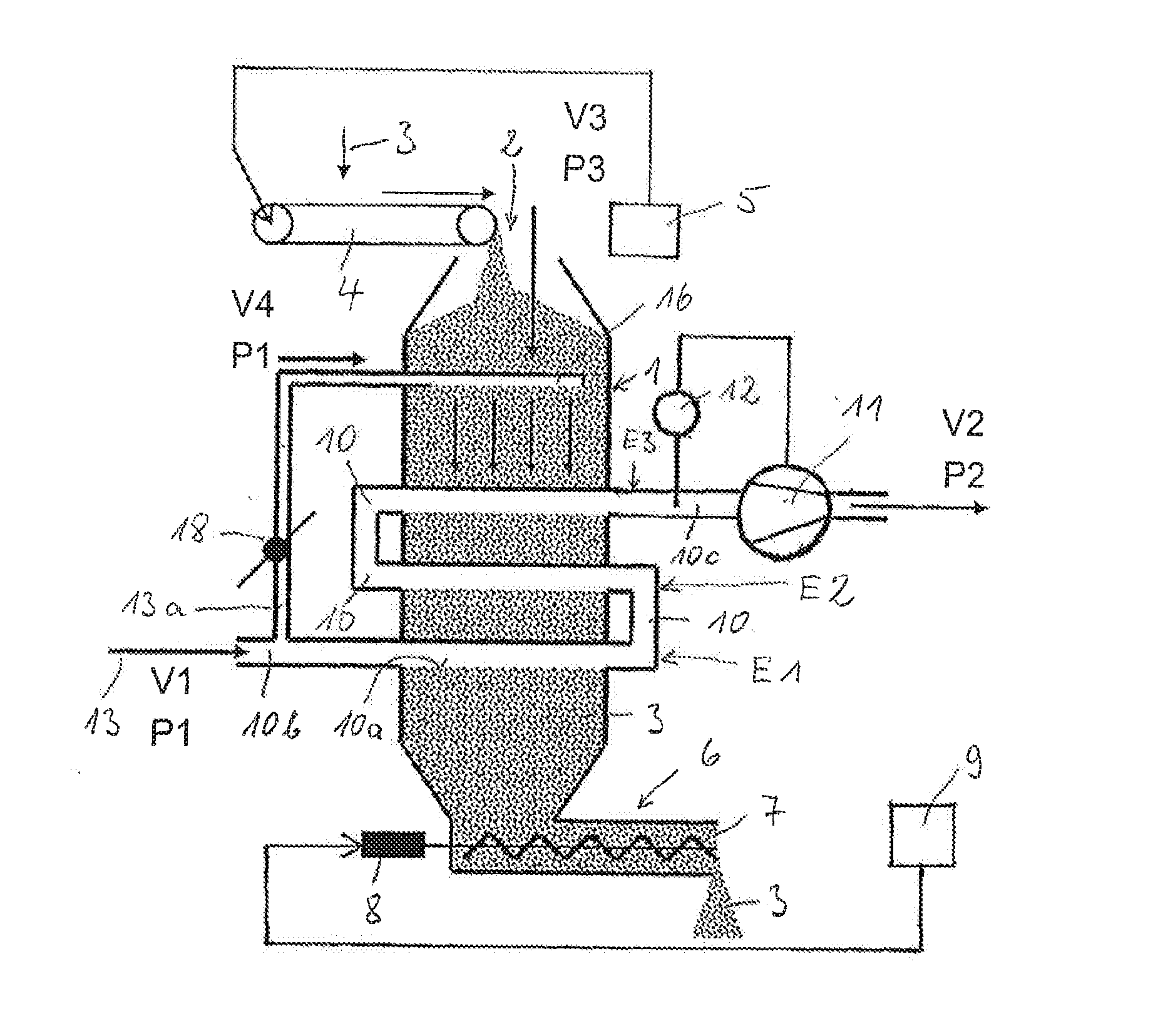
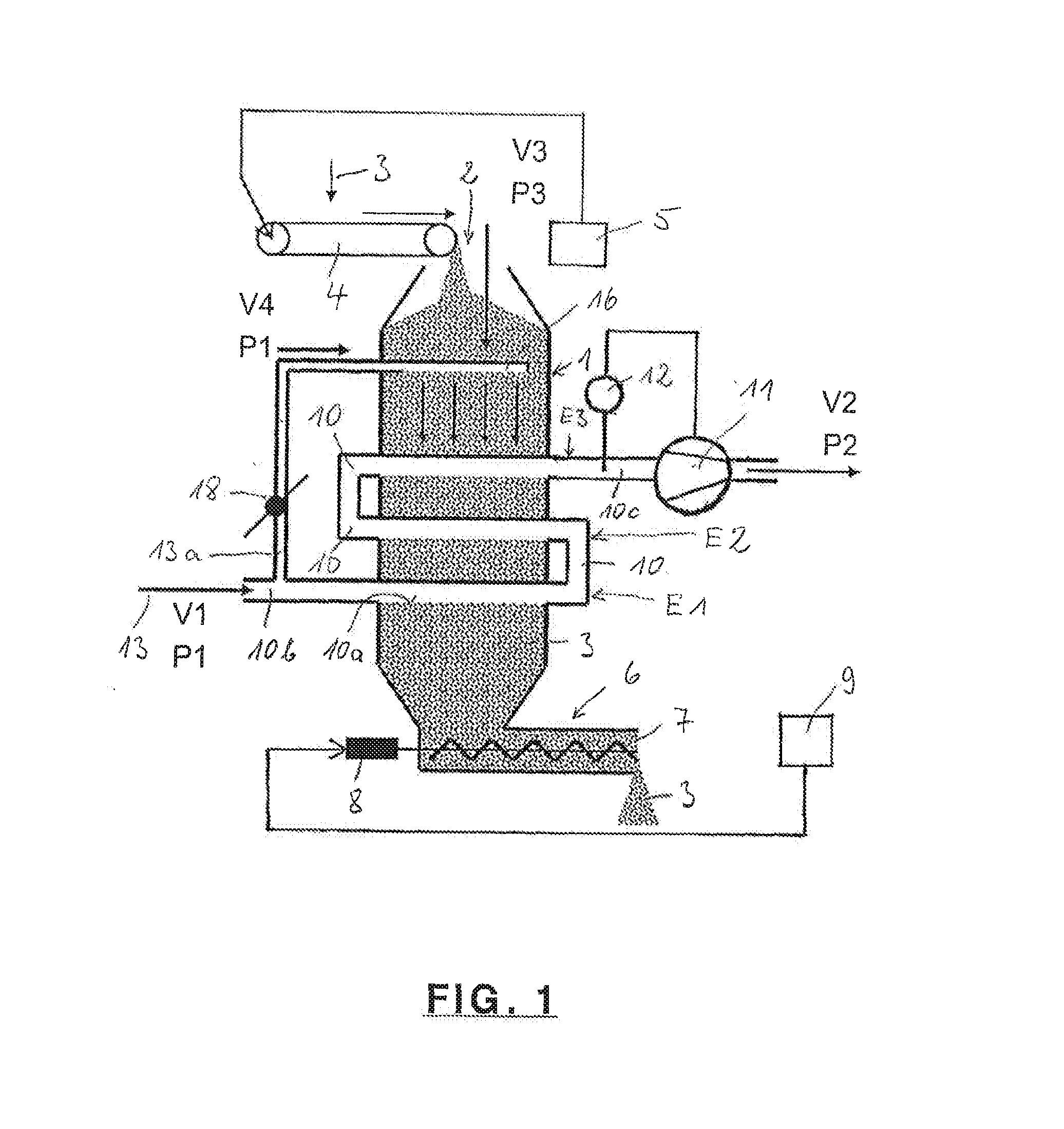
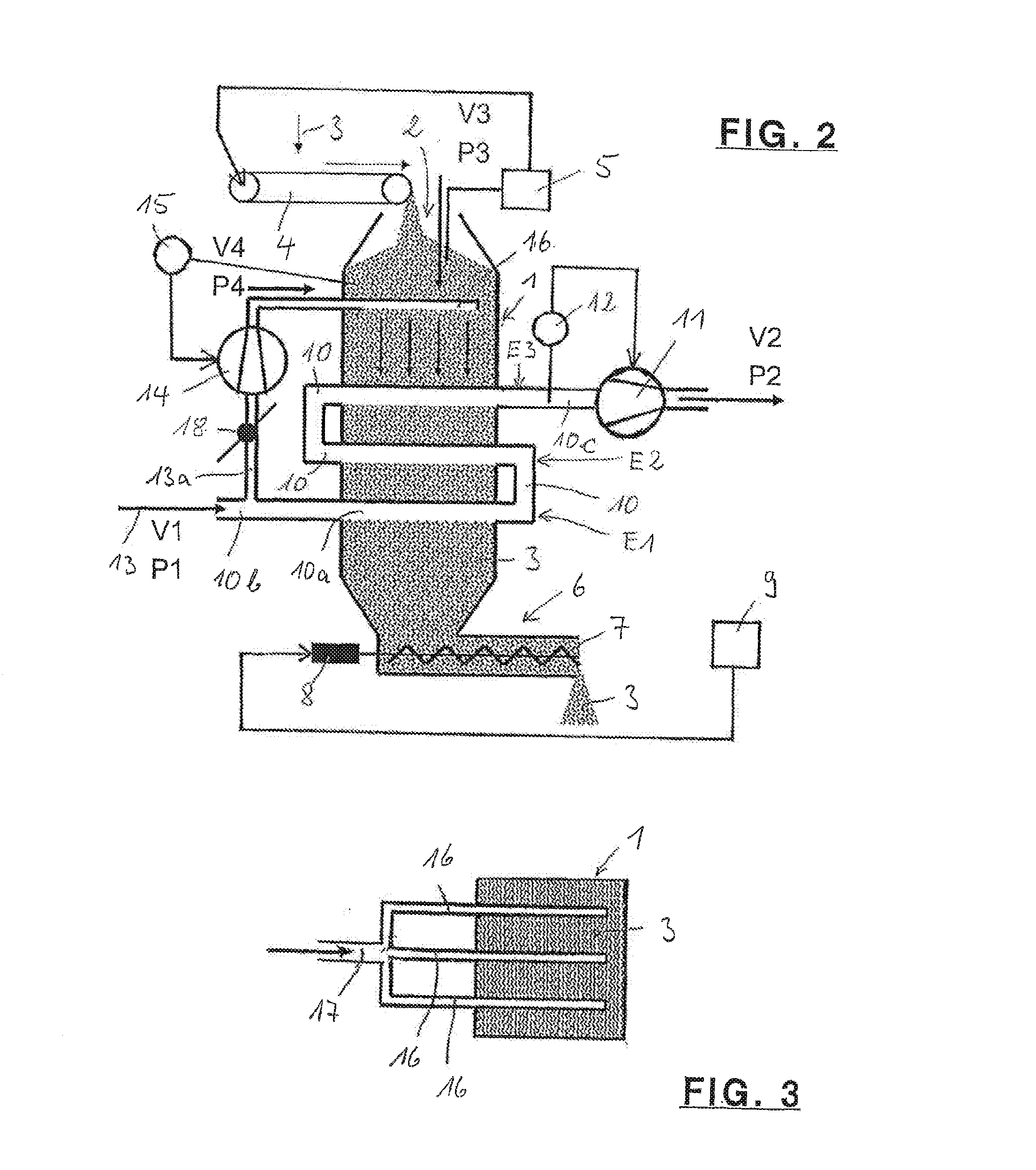
The present invention relates to a device for preheating particulate charging material for glass melting installations. The device has a low constructive height and volume, and minimizes the suctioning in of environmental air as false air and contamination. The device includes an exhaust gas supply line with a branch in the form of an outlet line for drawing off part of the high-pressure exhaust gases. This outgoing gas is connected to a sealing gas line placed above the charging material to prevent the suctioning of false air. The device also includes an induced draft to compensate for pressure losses during the conducting of the hot gases through the heat exchanger. A throttle is provided to adjust the quantity of the branched-off partial flow. The sealing gas lines are sealed at their ends inside the preheating shaft to direct the exit of the hot gases into the charging material. A pressure sensor is connected to the device to regulate the drawing off of the exhaust gases via the sealing gas lines. Overall, the device has improved energy efficiency and minimizes the impact on the environment.

Problems solved by technology

The preheating of charging material before its feeding into glass melting installations presents, with regard to its parameters and geometries, a complex and difficult-to-control constellation of influences from the areas of chemistry and physics.
The consequences range from clumping of the charging material up to process disturbances that are difficult to remedy.
In addition, false air suctioned from the atmosphere can also be disturbing, because it has for example a negative influence on the thermal balance, or promotes the release of dust and blocks degasification.
Due to the series connections of the flow paths and the use of a suction ventilator, an underpressure is produced in the system that further reinforces the undesirable effect of the drawing in of false air.

Method used


Image

  • Device for preheating charging materials for glass melting facilities
  • Device for preheating charging materials for glass melting facilities
  • Device for preheating charging materials for glass melting facilities

Examples


Embodiment Construction

[0019]FIG. 1 shows a preheating shaft 1 that has at its upper end a charging opening 20 for charging material 3, which forms a sinking column in preheating shaft 1. The supply of charging material takes place via a belt conveyor 4 whose conveying speed is regulated via a filling state sensor 5 in such a way that charging opening 2 does not become sealed. At the lower end, there is situated a discharge device 6 for the preheated charging material 3. This device has a conveyor screw 7 driven by a motor 8. The rotational speed thereof, and thus the conveyed quantity per time unit, is controlled via a sensor 9 that is connected to a filling state measuring device at a tub for the glass melt, which is not shown. Preheating shaft 1 is outwardly thermally insulated, so that the greater part of the supplied quantity of heat is transmitted to charging material 3. The movement of this material in preheating shaft 1 takes place through the action of gravity.

[0020]The preheating of charging mat...


PUM


Abstract

A device for preheating charging material for glass melting installations using its exhaust gases, having a vertical preheating shaft through which a heat exchanger extends conducting exhaust gases, the shaft upper end having a charging material opening, the lower end having a preheated charging material discharge device, the inlet of the heat exchanger connected to an exhaust gas supply line and the outlet connected to an exhaust gas outlet line. To recuperate a high portion of the exhaust gas heat, and to reduce environmental contamination and the suctioning of environmental air as false air, the exhaust gas supply line has an outlet line branch for drawing oft part of the hot gases and the outlet line is connected to a downwardly open sealing gas line in the region of the charging material above the heat exchanger exhaust gas passage for the hot gas emission into the charging material.

Description

CROSS-REFERENCES TO RELATED APPLICATIONS[0001]This application claims the benefit of German patent application No. 10 2010 055 685.8 filed on Dec. 22, 2010, the entire disclosures of which are incorporated herein by way of reference.BACKGROUND OF THE INVENTION[0002]A device for preheating particulate charging material for glass melting installations using the exhaust gases thereof, having a vertical preheating shaft through which there extends a heat exchanger through which the exhaust gases are conducted, the exhaust gas passage of the heat exchanger, which is protected against the penetration of particles, having openings along its circumference, and the upper end of the preheating shaft having a charging opening for the charging material, and the lower end having a discharge device for the preheated charging material, and the inlet of the at least one exhaust gas passage of the heat exchanger being connected to a supply line and the outlet being connected to an outlet line for th...

Claims


Application Information

Patent Timeline
IPC IPC(8): F27D7/02
CPCF27D7/02C03B3/023F28C3/14F28D7/0058F28D2021/0045Y02P40/50
Inventor LINDIG, MATTHIASSORG, HELMUT
Owner BETEILIGUNGEN SORG
Learn More