Ratchet-type tensioner

a ratchet-type, tensioner technology, applied in the direction of belts/chains/gears, mechanical instruments, belts/chains/gears, etc., can solve the problems of excessive tension, wear, noise, and eventual seizing of prior-art tensioners, and achieve excellent durability, reduce noise, and avoid excessive impact on ratchet-biasing springs.

Inactive Publication Date: 2013-11-21
TSUBAKIMOTO CHAIN CO
View PDF5 Cites 4 Cited by
  • Summary
  • Abstract
  • Description
  • Claims
  • Application Information

AI Technical Summary

Benefits of technology

[0019]When the second reaction force, i.e., a force that sets back the plunger when excessive tension is generated in the transmission medium, acts on the stop surfaces of the ratchet teeth, a component force acts on the stop counterface surfaces of the ratchet teeth, causing the piston to slide in a direction away from the plunger so that its teeth disengage the rack teeth of the plunger. Then, the rack teeth of the plunger slide over the counterface surfaces, clearing the ratchet teeth with which they are engaged, allowing the plunger to set back by a distance corresponding to one tooth. Setback displacement takes place smoothly without restriction on the movement of the plunger in the setback direction. Wear and damage, such as chipping of the rack teeth and ratchet teeth, which would otherwise occur as a result of excessive tension, are prevented. Excessive impact on the ratchet-biasing spring is also avoided. The ratchet mechanism therefore exhibits excellent durability.
[0020]The inclination angle of the stop surface is preferably smaller than the inclination angle of the sliding surface, the inclination angles being measured relative to the sliding direction of the piston. As a result, it is possible to block the plunger from setting back as a result of the first, lower level, reaction force, and thereby reduce noise caused by the setting back of the plunger.
[0021]Preferably, the ratchet mechanism comprises a means for preventing rotation of the piston in the circumferential direction of the piston receiving hole when the ratchet teeth and rack teeth are engaged. The rotation preventing means stops the outer circumferentia...

Problems solved by technology

In addition, the twist in the rod 524 can lead to faulty operation of the ratchet mechanism, and to erroneous assembly during manufacture and maintenance of the tensioner.
Thus, the prior art tensioner 500 experiences excessive tension, wear, ...

Method used


Image

  • Ratchet-type tensioner
  • Ratchet-type tensioner
  • Ratchet-type tensioner

Examples


Embodiment Construction

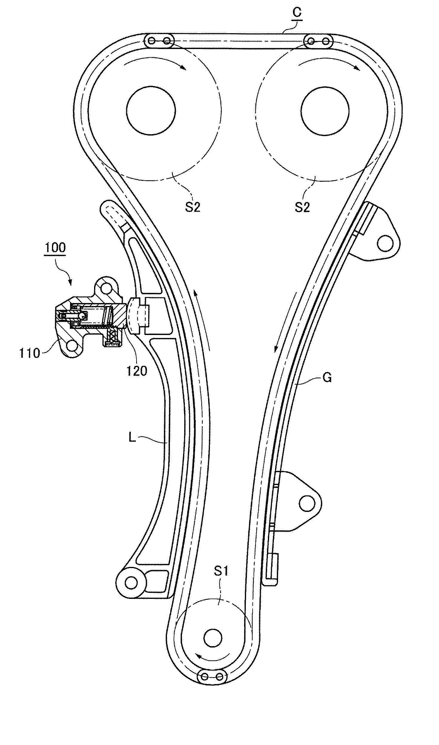
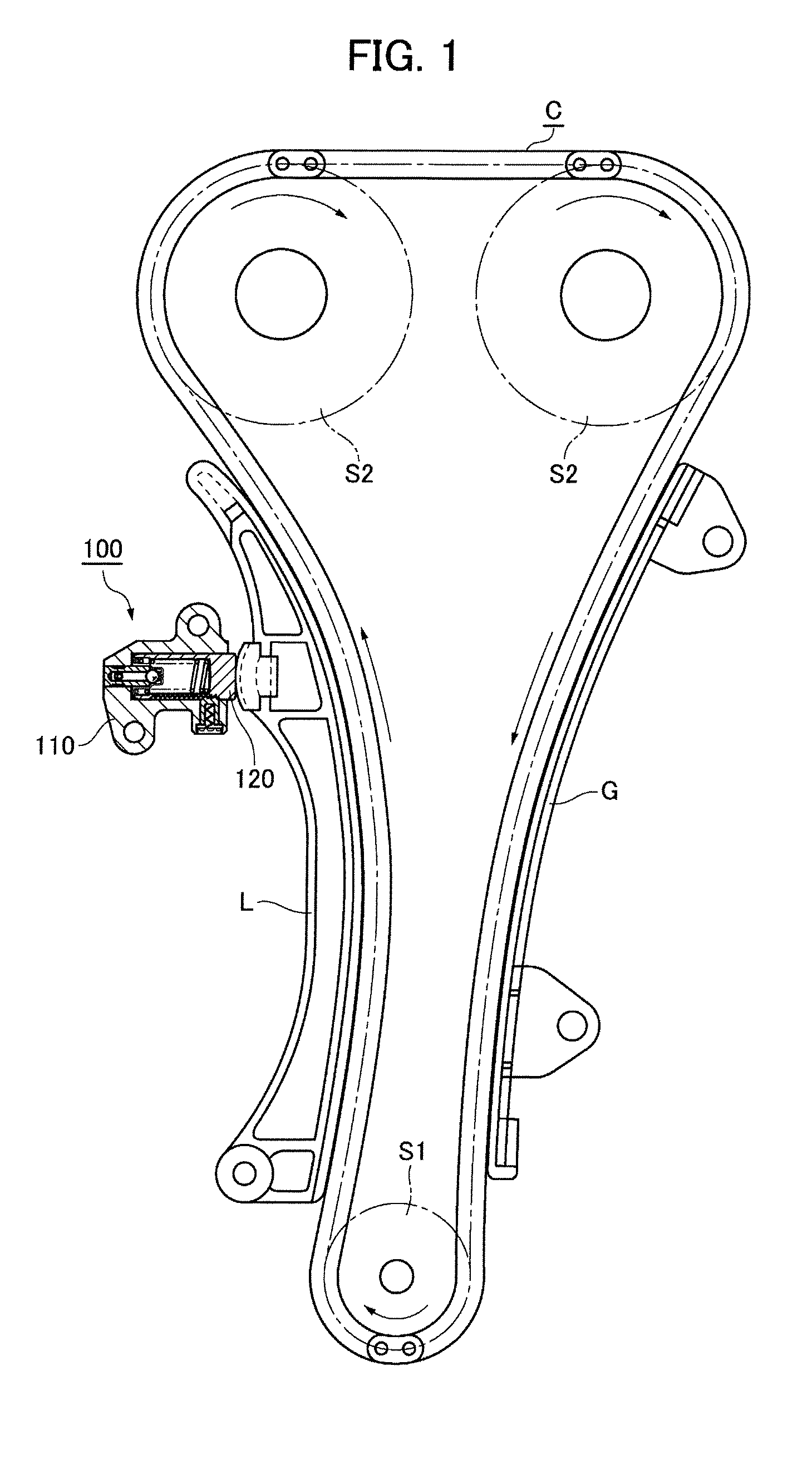
[0045]As shown in FIG. 1, the ratchet-type tensioner 100 of the invention is attached to an engine (not shown) on a slack side of a timing chain C which is engaged with a sprocket S1 rotated by a crankshaft and a pair of driven sprockets S2 fixed to camshafts.

[0046]The ratchet-type tensioner 100 has a housing 110 and a plunger 120 that slidably projects out of a front surface of the housing 110. The plunger 120 applies tension to the slack side of the timing chain C, i.e., the side that travels from the crankshaft sprocket S1 toward one of the camshaft sprockets S2. The plunger applies tension through a movable lever L on which the chain slides, and which is pivoted on the engine block, and presses the plunger 120 at a location remote from the lever's pivot axis.

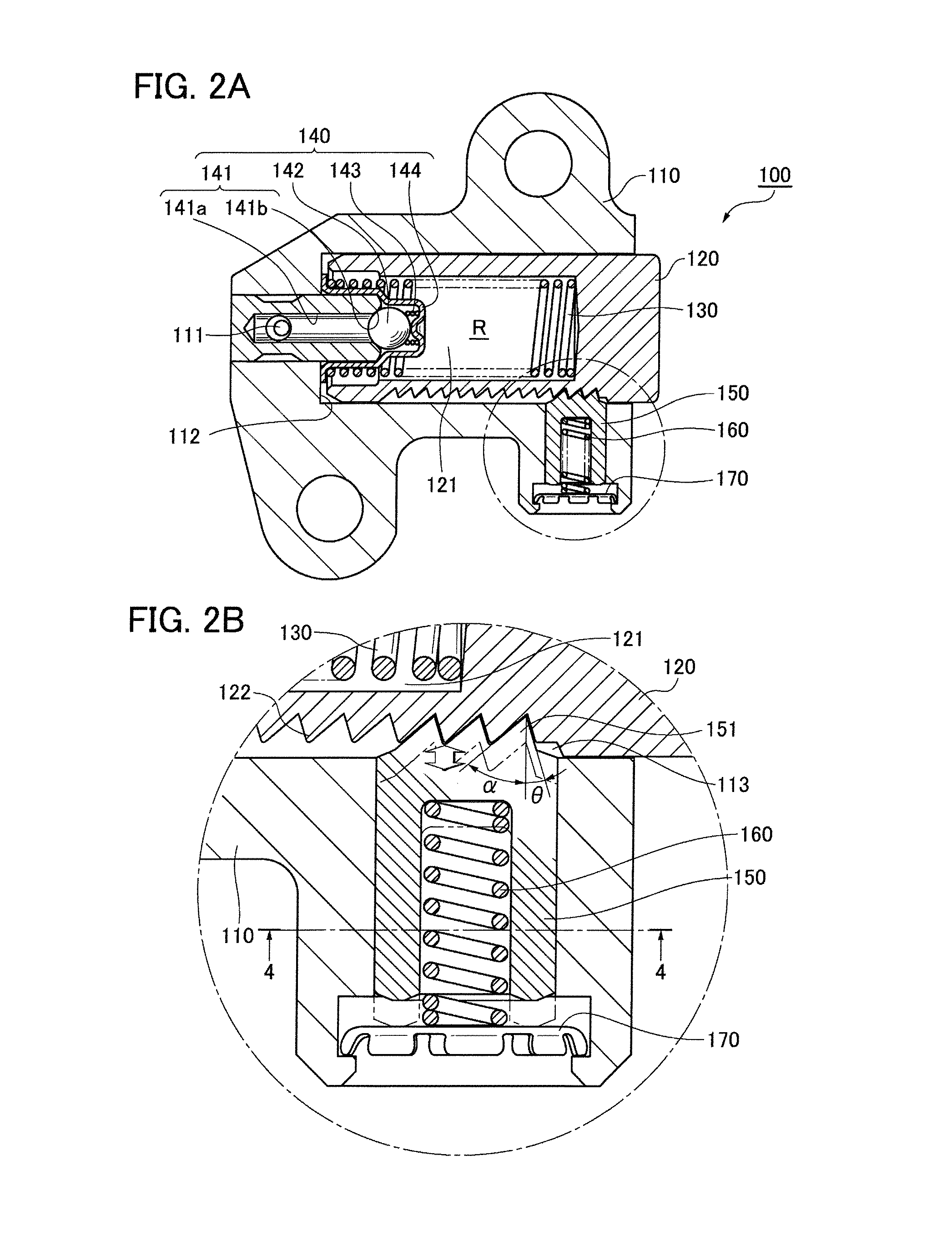
[0047]The basic configuration of the housing 110 of the tensioner 100 may be one that supplies oil under pressure from an oil pump (not shown) to the oil supply passage 111 formed within the housing 110, or one that has a co...


PUM


Abstract

In a ratchet-type tensioner having a plunger with rack teeth formed thereon and a piston with ratchet teeth that engage the rack teeth, the ratchet teeth can be disengaged from the rack teeth by insertion of a tool through a tool insertion hole in the tensioner housing and exerting a prying action on the toothed end of the piston to move the piston away from the plunger. Alternatively if an oblique camming surface is formed on the toothed end of the piston, the ratchet teeth can be disengaged from the rack teeth by pushing the tool inward against the oblique camming surface. The piston and the hole in which it slides are shaped to prevent rotation of the piston. The ratchet teeth on the piston and the rack teeth on the plunger can be oblique to allow setback of the plunger when excessive force is exerted on the plunger.

Description

FIELD OF THE INVENTION[0001]This invention relates to a ratchet-type tensioner for applying tension to an endless, flexible, transmission medium such as a timing chain for driving one or more camshafts in an internal combustion engine.BACKGROUND OF THE INVENTION[0002]A typical ratchet-type tensioner applies tension to a timing chain by exerting force on the chain by means of a plunger which is movable along an advancing and setback direction, in a plunger accommodating hole in the tensioner housing. The plunger is biased in the advancing direction by a spring and external hydraulic pressure provided by oil in a chamber formed by the tensioner housing and the plunger.[0003]A typical prior art ratchet-type tensioner is disclosed in Japanese Utility Model No. 2559664, and shown in FIG. 16. In the tensioner 500, a plunger 514 is slidable in a plunger-accommodating hole in a housing 512, and protrudes from the housing, being biased in the advancing direction by a spring 518 and by oil pr...

Claims


Application Information

Patent Timeline
IPC IPC(8): F16H7/08
CPCF16H7/0848F16H2007/0806F16H2007/0812F16H2007/0853F16H2007/0859
Inventor YOSHIDA, OSAMUKUREMATSU, YUJIMAEDA, MUNEHIROISHII, AKIRA
Owner TSUBAKIMOTO CHAIN CO
Why Eureka
Try Eureka