Steel gear and manufacturing method for the same

a manufacturing method and gear technology, applied in heat treatment equipment, furnaces, hoisting equipment, etc., can solve the problems that steel gears without sufficient dimensional accuracy cannot be produced, and achieve high dimensional accuracy, high strength, and increased internal hardness

Active Publication Date: 2013-11-28
AISIN AW CO LTD
View PDF2 Cites 2 Cited by
  • Summary
  • Abstract
  • Description
  • Claims
  • Application Information

AI Technical Summary

Benefits of technology

[0021]According to the above manufacturing method, since the region including the carburized layer and having a greater depth in the direction inward from the tooth bottom of the toothed shape of the outer peripheral surface than the depth of the carburized layer is partially subjected to high-frequency quenching, internal hardness is increased. Accordingly, a steel gear having high dimensional accuracy and high strength can be produced which is suitable for, e.g., high torque transfer gears such as differential gears for which high dimensional accuracy is required and in which not only the surface layer of the toothed shape but also the inside thereof are subjected to a stress. Moreover, strength can be increased to approximately the same extent without performing a shot-peening treatment, as compared to steel gears with the same sha...

Problems solved by technology

However, in the case where the conventional “carburization/slow cooling/high-frequency quenching treatment” is simply applied to the steel gear material having the flange portion coupled to the central position of the inner peripher...

Method used


Image

  • Steel gear and manufacturing method for the same
  • Steel gear and manufacturing method for the same
  • Steel gear and manufacturing method for the same

Examples


embodiments

[0067]Steel gears and manufacturing methods thereof according to embodiments will be specifically described with reference to the accompanying drawings. The steel gears of the embodiments are applied to differential gears. Reference characters are used as appropriate.

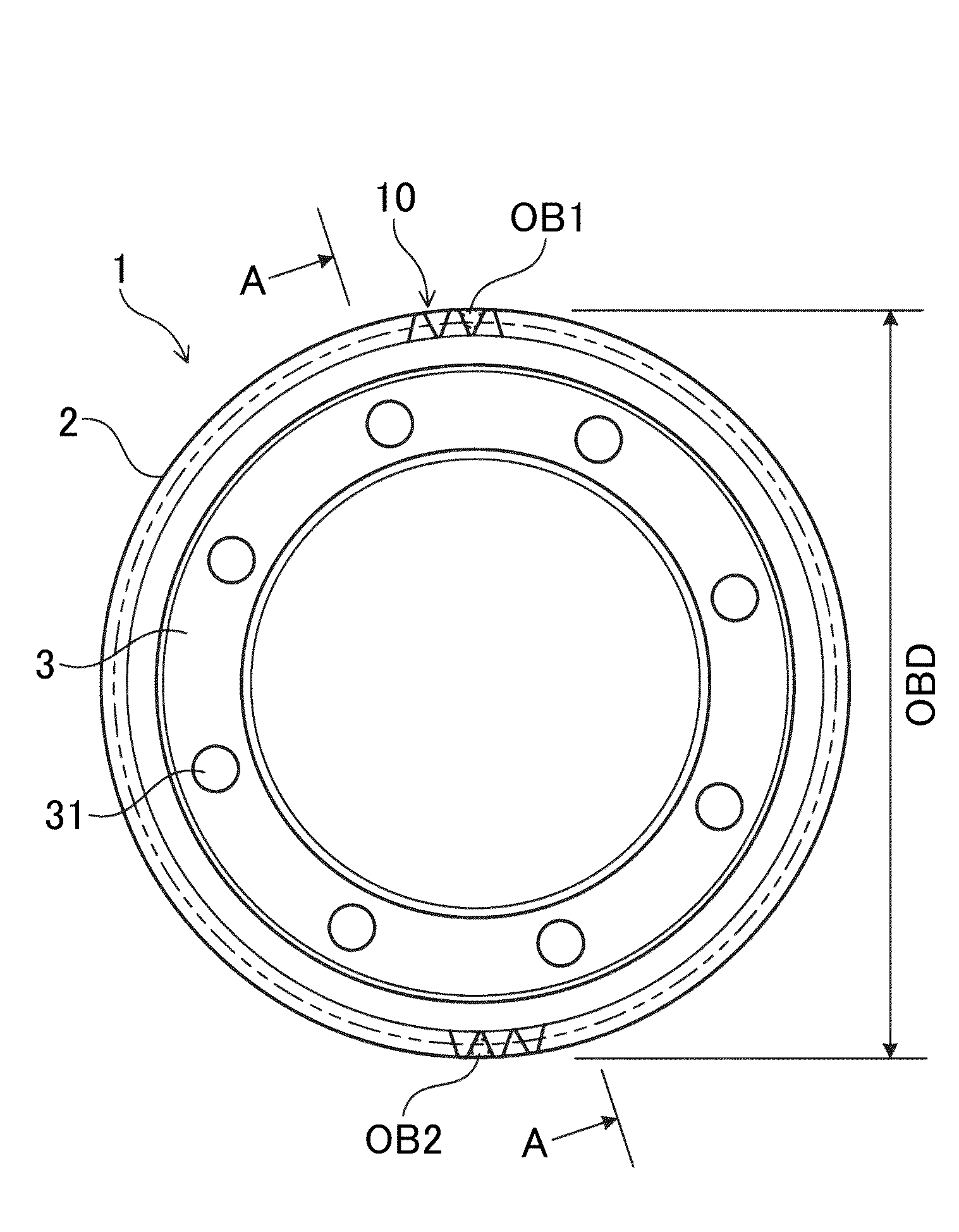
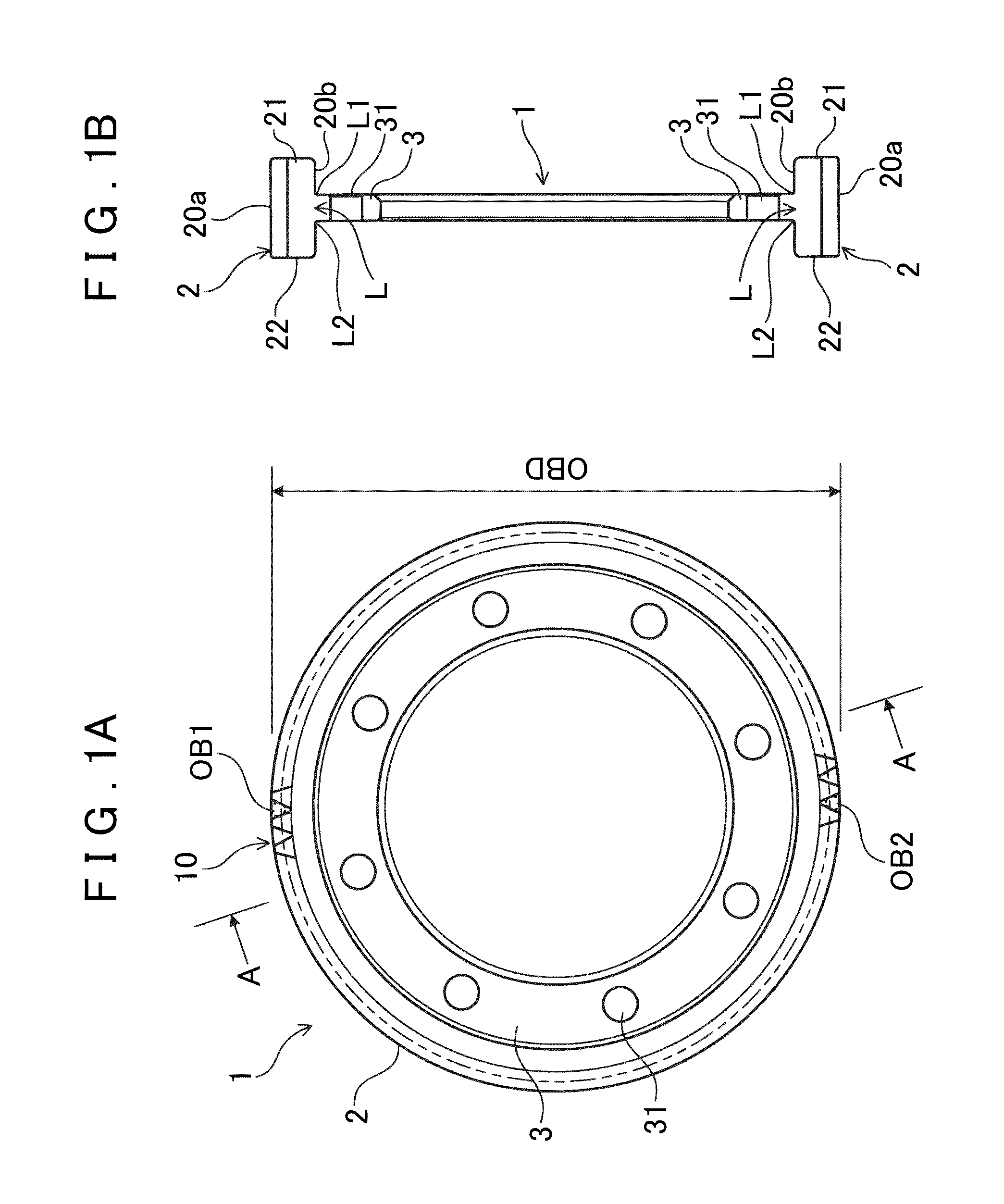
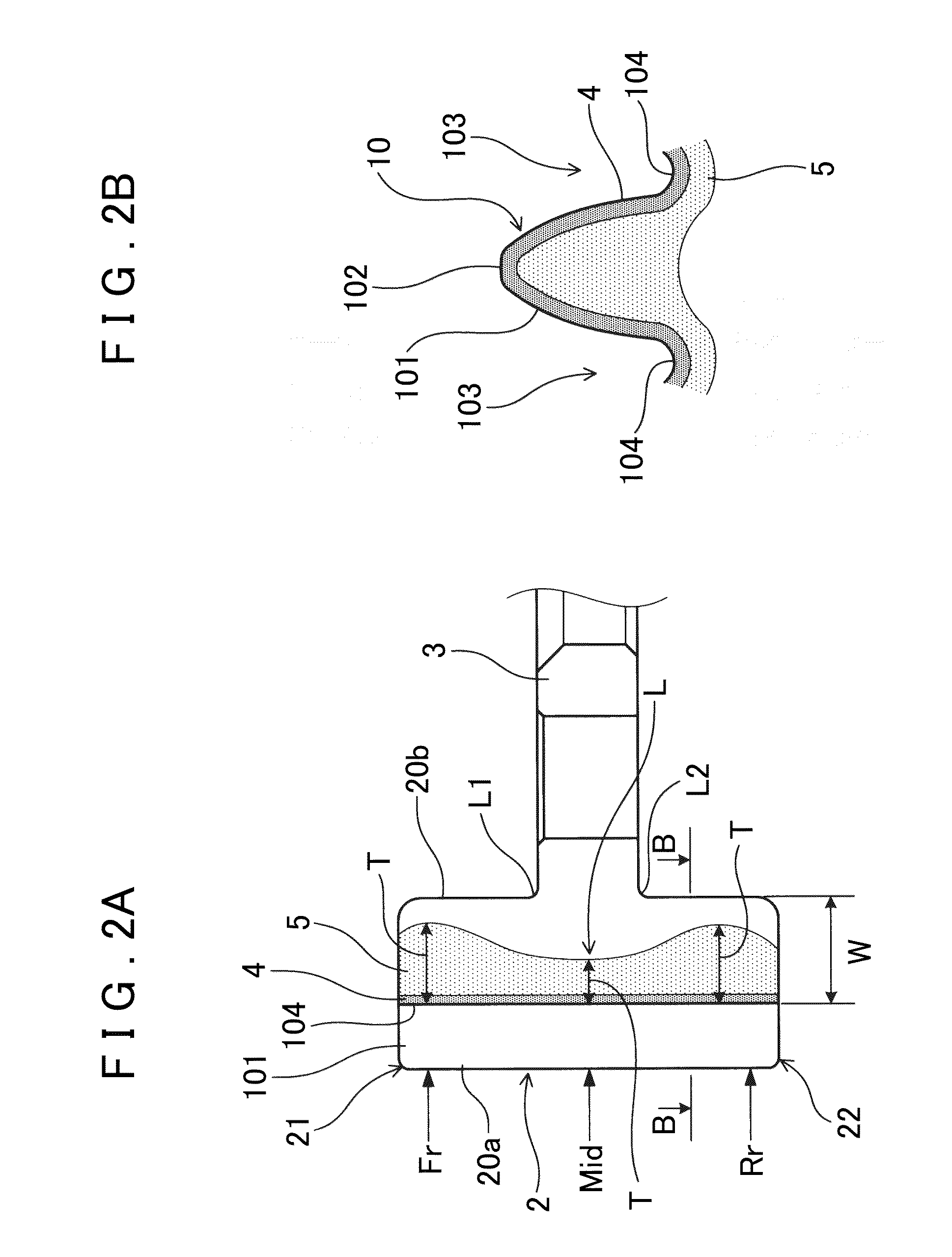
[0068]First, a schematic configuration of a steel gear according to a first embodiment will be described. As shown in FIGS. 1A and 1B, a steel gear 1 has a substantially cylindrical outer peripheral ring portion 2 having a toothed shape 10 formed on an outer peripheral surface 20a, and a flange portion 3 extended radially inward from an inner peripheral surface 20b of the outer peripheral ring portion 2. The outer peripheral ring portion 2 includes a first protruding portion 21 protruding toward one side in the axial direction with respect to a coupling portion L with the flange portion 3, and a second protruding portion 22 protruding toward the other side in the axial direction with respect to the coupling portion L wi...


PUM


Abstract

A steel gear includes a substantially cylindrical outer peripheral ring portion having a toothed shape formed on its outer peripheral surface; and a flange portion extended radially inward from an inner peripheral surface of the outer peripheral ring portion. The steel gear has a thermal history layer formed in the outer peripheral ring portion, and the depth of the thermal history layer in the direction inward from the tooth bottom of the toothed shape of the outer peripheral surface is greater in the first protruding portion and the second protruding portion than in the coupling portion with the flange portion, and is substantially the same between the first protruding portion and the second protruding portion. As a result, even if the “carburization/slow cooling/high-frequency quenching treatment” is used as a manufacturing method of the steel gear, the steel gear has high dimensional accuracy.

Description

[0001]INCORPORATION BY REFERENCE[0002]The disclosure of Japanese Patent Application No. 2011-077746 filed on Mar. 31, 2011 including the specification, drawings and abstract is incorporated herein by reference in its entirety.BACKGROUND OF THE INVENTION[0003]The present invention relates to steel gears and manufacturing methods for steel gears.Description of the Related Art[0004]Conventionally, steel gears are used in various industrial fields. For example, differential devices for use in the automotive field have a large number of steel gears. There are steel gears having various shapes. For example, those gears are widely known in the art which include a cylindrical outer peripheral ring portion having a toothed shape formed on its outer peripheral surface, and a flange portion coupled to the central position of the inner peripheral surface of the outer peripheral ring portion in the axial direction.[0005]Steel gears are members for which high strength and wear resistance are requ...

Claims


Application Information

Patent Timeline
IPC IPC(8): C21D9/32F16H55/06
CPCC21D9/32F16H55/06C21D1/10C22C38/00C23C8/22C23C8/80F16H55/17Y02P10/25Y10T29/49467Y10T74/1987
Inventor OBAYASHI, KOJITAGUCHI, KEITAMIYAKE, YASUTAKAOGISO, TAKAAKI
Owner AISIN AW CO LTD
Why Eureka
Try Eureka