Vessel with Filter

a filter and valve technology, applied in the direction of valve operating means/releasing devices, sublimation, separation processes, etc., can solve the problems of clogging of the reaction chamber, inability to generate and convey precursor-containing vapor, and extended “down time" the effect of reducing pressure drop, reducing clogging, and increasing pressure drop

Active Publication Date: 2013-11-28
VERSUM MATERIALS US LLC
View PDF7 Cites 27 Cited by
  • Summary
  • Abstract
  • Description
  • Claims
  • Application Information

AI Technical Summary

Benefits of technology

[0013]The vessels and methods described herein provide one or more of the following benefits, one being that the surface area of the filters used prior to this invention were too small for the intended flow rates therethrough causing transport and entrainment of precursor onto the filter surface causing increasing pressure drop (across the filter) and often culminating in undesirable clogging of the filters. The large surface area of the 3-dimensional filters used in this invention provide for relatively lower pressure drops across them and reduced clogging.

Problems solved by technology

The vaporization of a solid precursor material presents difficulties in generating and conveying the precursor-containing vapor to the reaction chambers.
Typical difficulties encountered include, but are not limited to, deposit buildup within the vessel, vaporizer and / or delivery lines; condensation of liquid- or solid-phase material within the vessel, vaporizer and / or delivery lines, formation of “cold spots” within the interior of the vessel; and inconsistent vapor flow to downstream reaction chambers.
These difficulties may result in extended “down time” of the production equipment to remove liquid or particulate matter and may also produce relatively poor quality deposited films.

Method used


Image

  • Vessel with Filter
  • Vessel with Filter
  • Vessel with Filter

Examples


example 1

Results of Example 1

[0116]

DifferentialAccumulativeDifferentialAccumulativeParticlesParticlesParticles perParticles perSize, μmCountedCountedcm3cm30.161684460.61.60.22232780.81.00.352550.20.20.5330.00.0

[0117]The data indicates that a total of 446 particles were registered in all size channels >0.16 μm. This corresponds to −2 particle / cm3>0.16 μm. Thus installing the tubular particle barrier (filter) on the outlet of vessel reduced particles in the carrier gas by approximately 1000 times.

example 2

[0118]Sintering pentakis(dimethylamido)tantalum (PDMAT) in the vessel was performed as follows:

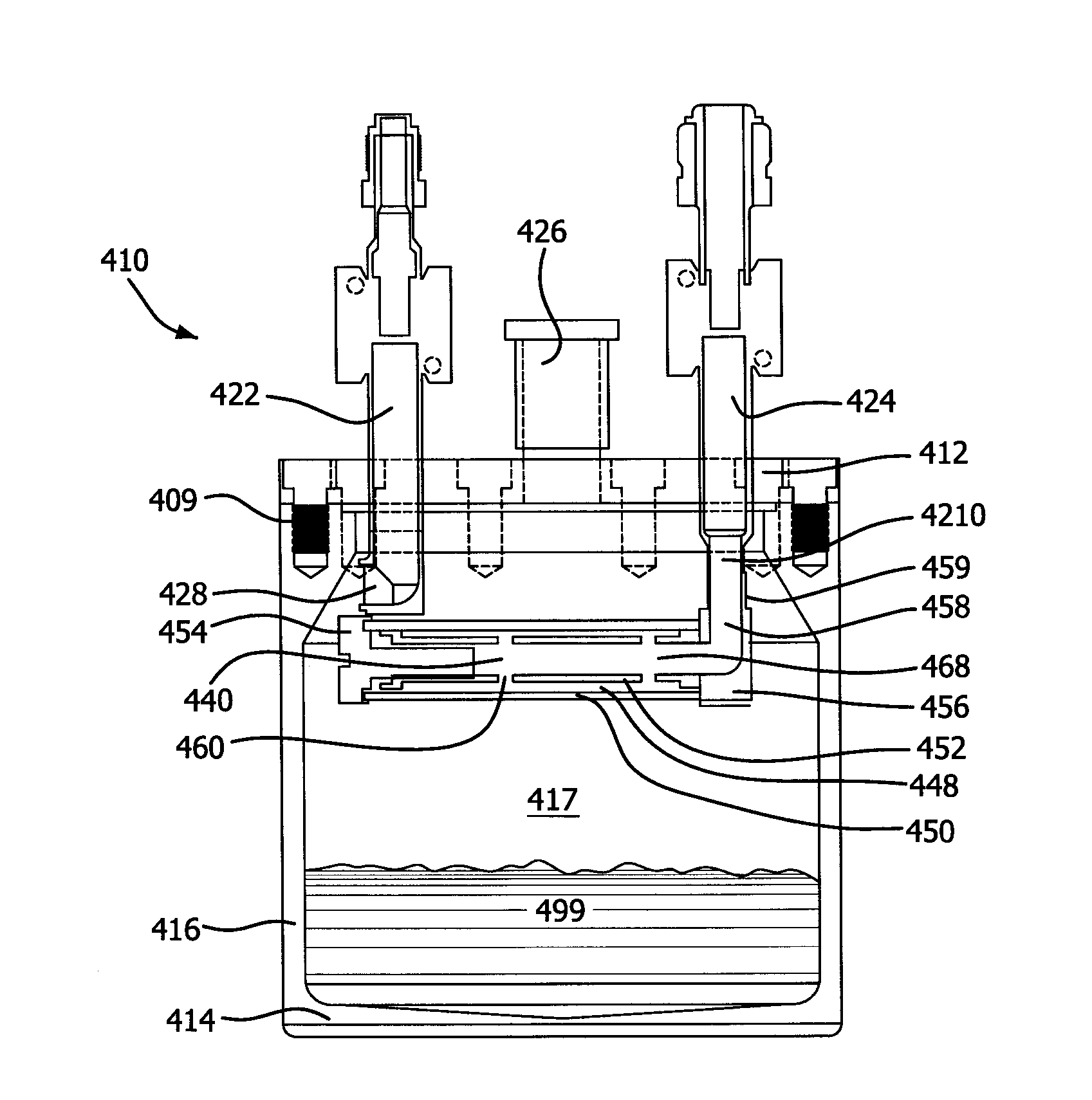
[0119]In the glove box 200 g of PDMAT was loaded into 1.2 L SS vessel equipped with a 90 degree elbow fitting inside the vessel on the inlet angled about 90 degrees relative to an axis of the vessel, and an outlet tube equipped with a SS tubular filter (particle barrier). The vessel was also equipped with the fill port and exterior valves coupled to inlet and outlet tubes. The vessel was heated for 4 hours at 90° C. under 1 psig of nitrogen to sinter PDMAT powder. After this sintering procedure the solid was inspected by rotating the vessel 120 degrees to observe for the presence of any loose particles, Loose powder was not observed. The loose powder was sintered into a solid cake by this procedure.

example 3

[0120]Sintering pentakis(dimethylamido)tantalum (PDMAT) in the vessel was performed as follows:

[0121]Example 2 was repeated except the vessel was heated for 16 hours at 80° C. under 80 psig of nitrogen to sinter the PDMAT powder. After this sintering procedure the solid was inspected by rotating the vessel 120 degrees to observe for the presence of any loose particles. Loose powder was not observed; it was sintered into a solid cake during this procedure.


PUM

PropertyMeasurementUnit
surface areaaaaaaaaaaa
Surface Areaaaaaaaaaaa
temperaturesaaaaaaaaaa

Abstract

A vessel for conveying a precursor-containing fluid stream from a precursor material contained within the vessel, the vessel comprising: an interior volume defined by a top, one or more sidewalls, and a base; and at least one fluid outlet for vaporized precursor, and at least one particle barrier that defines at least one particle restricted space within the interior volume, wherein said particle barrier comprises at least one 3-dimensional filter. A method for using the apparatus is also disclosed.

Description

CROSS-REFERENCE OF RELATED APPLICATIONS[0001]This application claims priority to and benefit of U.S. Provisional Ser. No. 61 / 652,236, filed May 27, 2012, and U.S. Provisional Ser. No. 61 / 764,851, filed Feb. 14, 2013, which are incorporated herein by reference in their entirety.BACKGROUND OF THE INVENTION[0002]Deposition processes such as, for example, chemical vapor deposition (CVD) and atomic layer deposition (ALD) processes, are used in one or more steps during the manufacture of a semiconductor device to form one or more films or coatings on the surface of a substrate. In a typical CVD or ALD process, a precursor source that may be in a solid and / or liquid phase is conveyed to a reaction chamber having one of more substrates contained therein where the precursor reacts under certain conditions such as temperature or pressure to form the coating or film on the substrate surface.[0003]When a solid precursor material is used in a CVD or ALD process, the precursor material is typical...

Claims


Application Information

Patent Timeline
Patent Type & Authority Applications(United States)
IPC IPC(8): C23C16/455
CPCC23C16/455C23C16/4481C23C16/4485Y10T137/794Y10T137/4891C23C16/448C23C16/4412C23C16/4402B01D7/00H01L21/0262B01D46/02B01D46/2403B01D2275/203B01D2275/206B01D2279/00
Inventor BIRTCHER, CHARLES MICHAELSTEIDL, THOMAS ANDREWLEI, XINJIANIVANOV, SERGEI VLADIMIROVICH
Owner VERSUM MATERIALS US LLC
Why Eureka
Try Eureka