Integrated cooling and climate control system for an offshore wind turbine

a technology of integrated cooling and climate control system, which is applied in the direction of air heaters, other heat production devices, lighting and heating apparatus, etc., to achieve the effect of effective and efficient removal of hea

Active Publication Date: 2013-12-05
ADWEN OFFSHORE SL
View PDF7 Cites 10 Cited by
  • Summary
  • Abstract
  • Description
  • Claims
  • Application Information

AI Technical Summary

Benefits of technology

[0012]The inlet and outlet pipes between the upper cooling circuit and the reservoir extend through openings in the reservoir lid and are adapted to freely hang inside the reservoir chambers so that the inlet and outlet pipes may be displaced as the wind turbine moves. The reservoir is configured so that its vertical axis and that of any associated lid are coincident with the nacelle yaw axis. The system is adapted so that when the nacelle yaws, the inlet and outlet pipes freely rotate inside their respective reservoir chambers along with the reservoir lid in order to maintain sufficient circulation of the coolant fluid in the upper cooling circuit.
[0014]The system serves to effectively and efficiently remove heat from the nacelle air and heat generating structures in the nacelle and utilize sea water at the lower portion of the tower as a heat sink. The circulation of the coolant fluid is maintained as the nacelle yaws.

Problems solved by technology

The frequent yawing of the nacelle interferes with the circulation of the coolant from the nacelle to a heat exchanger, particularly on a lower portion of the turbine such as the tower bottom or the sea.

Method used


Image

  • Integrated cooling and climate control system for an offshore wind turbine
  • Integrated cooling and climate control system for an offshore wind turbine
  • Integrated cooling and climate control system for an offshore wind turbine

Examples


Embodiment Construction

[0021]As an initial comment, it is noted that the term “pipes” as used herein is non-limiting and refers to other conduits and like devices known in the art including coils, tubes, and other means known in the art.

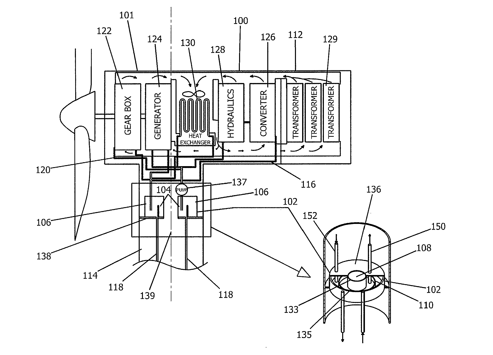
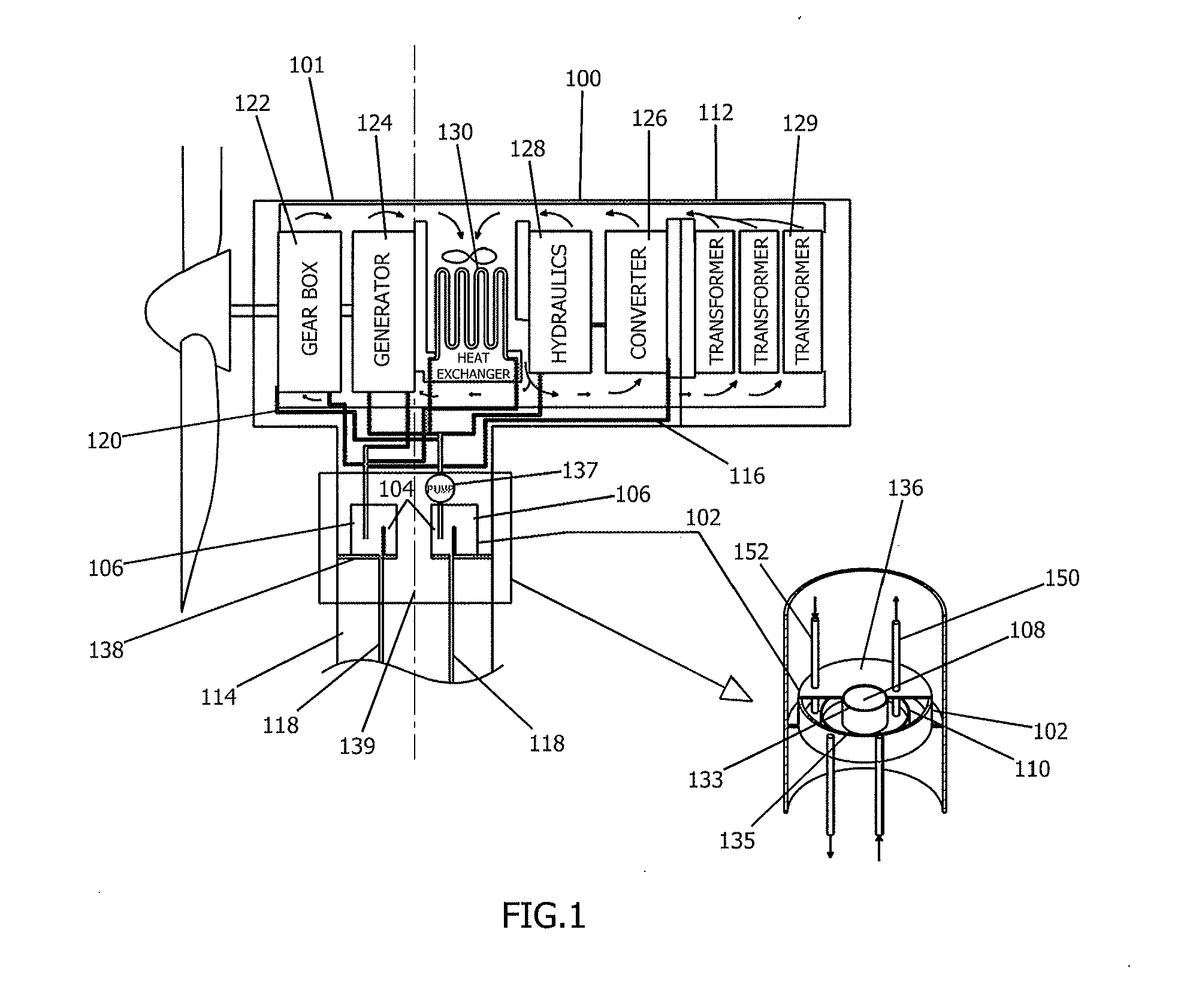
[0022]FIGS. 1, 1a, and 2 show the integrated cooling and climate control system 100 for an offshore wind turbine 101 according to embodiments of the present invention. The system 100 comprises a reservoir 102 having first 104 and second 106 chambers. The reservoir 102 is preferably positioned in an upper region of the tower 114 of the wind turbine 101 just below the nacelle 112.

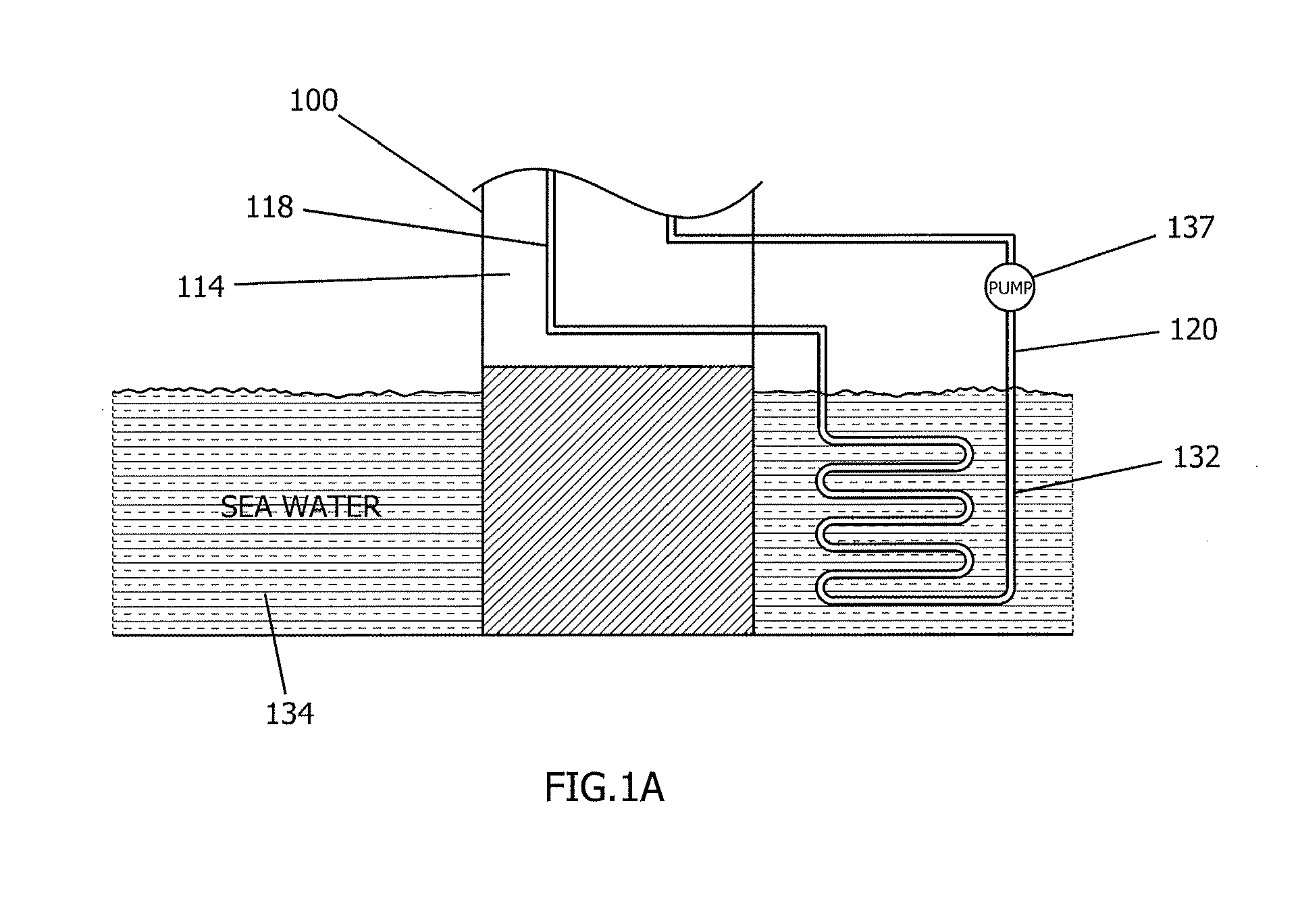
[0023]The integrated cooling and climate control system 100 comprises an upper cooling circuit 116 formed by a series of pipes which extend upwardly from the reservoir 102 through the nacelle 112 and then downwardly back to the reservoir. The integrated cooling and climate control system 100 is adapted to distribute a coolant fluid 120 from a first chamber 104 of the reservoir 102 through the nacell...


PUM

PropertyMeasurementUnit
hydraulic pressureaaaaaaaaaa
energyaaaaaaaaaa
voltageaaaaaaaaaa

Abstract

An integrated cooling and climate control system for an offshore wind turbine featuring a reservoir having first and second chambers located in an upper region of the tower. Upper and lower cooling circuits distribute coolant fluid through heat generating structures in the nacelle to a lower portion of the wind turbine where the heated coolant fluid is thermally connected to a sea water heat sink. The cooled coolant fluid is then distributed back to the reservoir. The reservoir has a hollow center and is positioned on a platform having a hollow center. The inlet and outlet pipes of the upper cooling circuit freely hang inside the reservoir chambers so that they may be displaced as the nacelle yaws in order to maintain sufficient circulation of the coolant fluid in the upper cooling circuit. In jacket foundation configurations, the tubular support structures may serve as the lower cooling circuit pipes.

Description

BACKGROUND OF THE INVENTION[0001]1. Field of the Invention[0002]The present invention generally relates to an integrated cooling and climate control system for an offshore wind turbine system.[0003]2. Related Art[0004]A wind turbine converts the kinetic energy of wind into electrical energy through its rotor, drivetrain, electrical generator, and converter. An electrical transformer converts the low voltage output from the converter into a high voltage output before the electricity is sent to the substation at the wind farm.[0005]The wind turbine nacelle houses the mechanical and electrical components, namely the drivetrain, the electrical generator, the converter, and the transformer, and the components of the hydraulic system needed for blade pitching and nacelle yawing. These components generate a significant amount of heat when the wind turbine is operating. In order to ensure that the components continue to operate efficiently and do not overheat, the heat generated by these co...

Claims


Application Information

Patent Timeline
Patent Type & Authority Applications(United States)
IPC IPC(8): F03D11/00C09K5/10F28D15/00
CPCF03D13/25F03D80/60F03D80/88F05B2260/205F28D15/00Y02E10/72
Inventor SABHAPATHY, PERIMORENO BENITO, EDUARDOJORSTAD, DAG
Owner ADWEN OFFSHORE SL
Why Eureka
Try Eureka