
Magnetic field sensor

Inactive Publication Date: 2013-12-05
ROBERT BOSCH GMBH
View PDF5 Cites 7 Cited by
  • Summary
  • Abstract
  • Description
  • Claims
  • Application Information

AI Technical Summary

Benefits of technology

This patent relates to a technology that improves the ability of magnetic sensors to quickly change magnetic fields. This is done by giving each sensor a unique anisotropy, which allows for a more uniform magnetic response. This anisotropy is created by simultaneously depositing two layers of magnetic material onto a substrate, with one layer having a 45-degree angle to its surface. This results in a more uniform magnetic response and reduces the need for positioning or rotating the substrate during the process. Additionally, the patent suggests using a single coil to determine magnetic reversal, which reduces manufacturing costs while still maintaining the ability to change magnetic fields.

Problems solved by technology

The magnetic anisotropy may be formed simultaneously on the substrate or in one step for both magnetic sensor cores, which results in shortening and simplification of the manufacture and furthermore in reduced manufacturing costs.

Method used


Image

  • Magnetic field sensor
  • Magnetic field sensor
  • Magnetic field sensor

Examples


Embodiment Construction

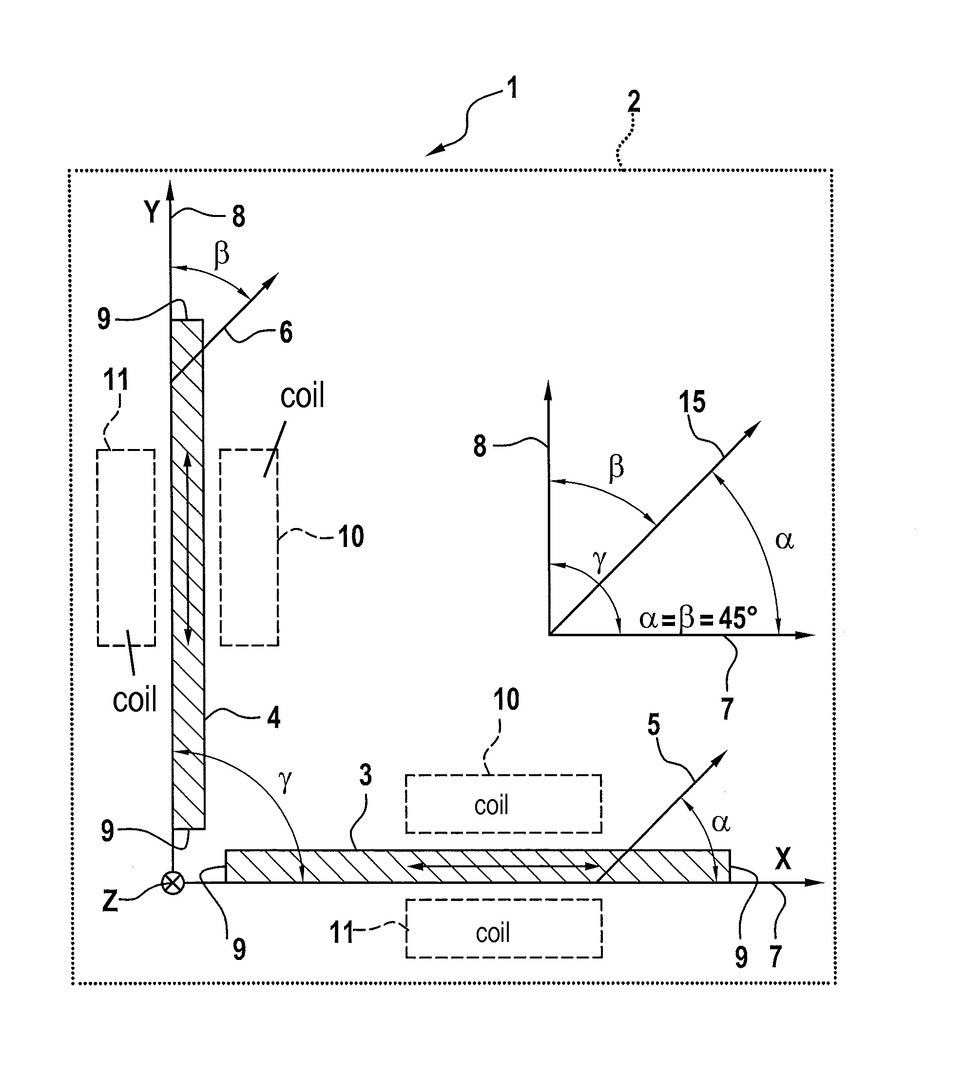
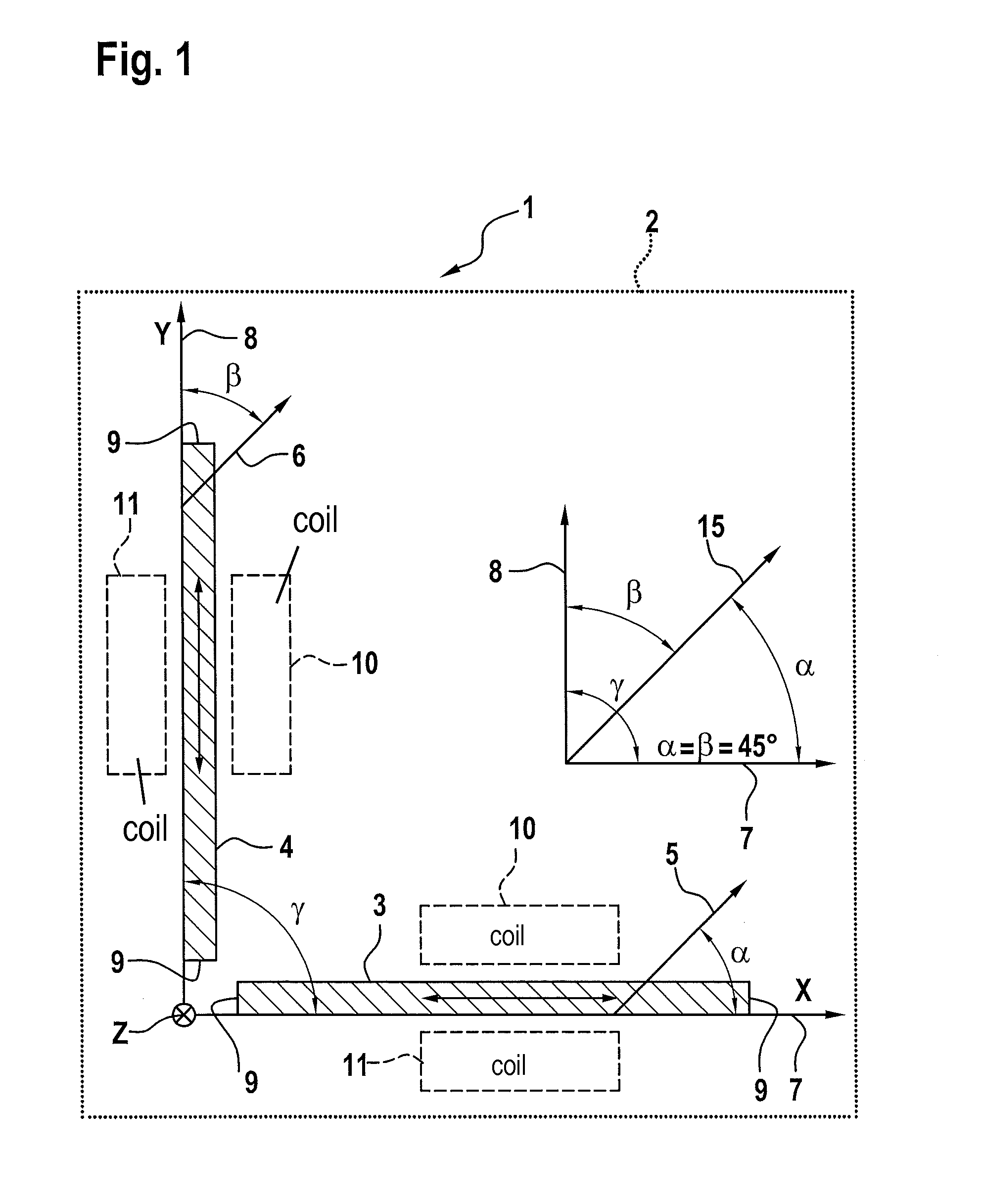
[0017]FIG. 1 shows a schematic diagram of a magnetic field sensor 1 according to one specific embodiment of the present invention. Magnetic field sensor 1 is shown in a top view.

[0018]A so-called flux gate is a conventional technology for detecting the Earth's magnetic field or for measuring relatively weak magnetic fields. There are various specific embodiments in this case. One particularly simple specific embodiment includes only two coils and a ferromagnetic core. The first coil is operated using a delta current. If a specific field strength in the core is exceeded, its magnetism is reversed and generates a voltage pulse in the second core. The field strength to be measured may be inferred from the occurrence with respect to time of the voltage pulse in relation to the delta current. Since the magnetic reversal is to be completed suddenly, the core is magnetized in the direction of its magnetic preferential direction. This preferential direction is normally established during th...


PUM

PropertyMeasurementUnit
Angleaaaaaaaaaa
Angleaaaaaaaaaa
Angleaaaaaaaaaa

Abstract

A magnetic field sensor having a first magnetic sensor core for measuring a magnetic field in a first measuring direction, and a second magnetic sensor core for measuring a magnetic field in a second measuring direction, the first and second magnetic sensor cores having a shared magnetic anisotropy.

Description

CROSS REFERENCE[0001]The present application claims the benefit under 35 U.S.C. §119 of German Patent Application No. DE 102012209232.3 filed on May 31, 2012, which is expressly incorporated herein by reference in its entirety.FIELD[0002]The present invention relates to a magnetic field sensor.BACKGROUND INFORMATION[0003]A device for measuring the direction and / or strength of a magnetic field is described in German Patent Application No. DE 10 2008 042 800 A1. The device is situated on a substrate. A Hall sensor is situated on the surface of the substrate, which is provided for the purpose of detecting a magnetic field component Z, which acts substantially perpendicularly to the surface of the substrate. Furthermore, two flux gate sensors are provided, in order to detect a magnetic field component in the X-Y plane of the substrate. Therefore, together with the Hall sensor, three components may be determined in all three spatial directions.SUMMARY[0004]The present invention provides ...

Claims


Application Information

Patent Timeline
IPC IPC(8): G01R33/02G01R33/00
CPCG01R33/02G01R33/0052
Inventor REICHENBACH, FRANKFARBER, PAULNJIMONZIE, FREDERIC NJIKAMSCHATZ, FRANKPATAK, CHRISTIANWEISS, STEFANMARKTANNER, JOERG
Owner ROBERT BOSCH GMBH
Learn More