
Spectral characteristic measuring device, method for correcting spectral characteristic measuring device and program

a technology of spectral characteristic and measuring device, applied in the direction of optical radiation measurement, instruments, spectrometry/spectrophotometry/monochromator, etc., can solve the problems of thermal change and temporal change, and achieve the effect of rapid correction, high accuracy and accurate correction of efficiency differences

Active Publication Date: 2013-12-05
KONICA MINOLTA INC
View PDF1 Cites 14 Cited by
  • Summary
  • Abstract
  • Description
  • Claims
  • Application Information

AI Technical Summary

Benefits of technology

The spectral characteristic measuring device described in this patent can quickly and accurately correct changes in the spectral distribution of monochromatic light, using a predetermined relational expression. The device can easily determine the difference in efficiency between different light receiving elements, using a shift amount measurement. Additionally, the device can correct for the influence of sensitivity and diffraction efficiency, and accurately obtain the shift amount between the estimated intensity distribution and the second intensity distribution. Overall, the device provides a reliable and efficient tool for measuring spectral characteristics.

Problems solved by technology

However, the plastic molded article may cause thermal change and temporal change due to change in surrounding temperature, alleviation in internal stress after molding, and the like.

Method used


Image

  • Spectral characteristic measuring device, method for correcting spectral characteristic measuring device and program
  • Spectral characteristic measuring device, method for correcting spectral characteristic measuring device and program
  • Spectral characteristic measuring device, method for correcting spectral characteristic measuring device and program

Examples


Embodiment Construction

[0060]One embodiment of the present invention will be hereinafter described based on the drawings. In the figures, portions having similar configurations and functions are denoted with the same reference numbers, and redundant description will be omitted in the following description. Furthermore, the drawings are schematically illustrated, and the size, positional relationship, and the like of various structures in each figures are not accurately illustrated.

(1) Schematic Configuration of Spectral Reflection Characteristic Measuring Device

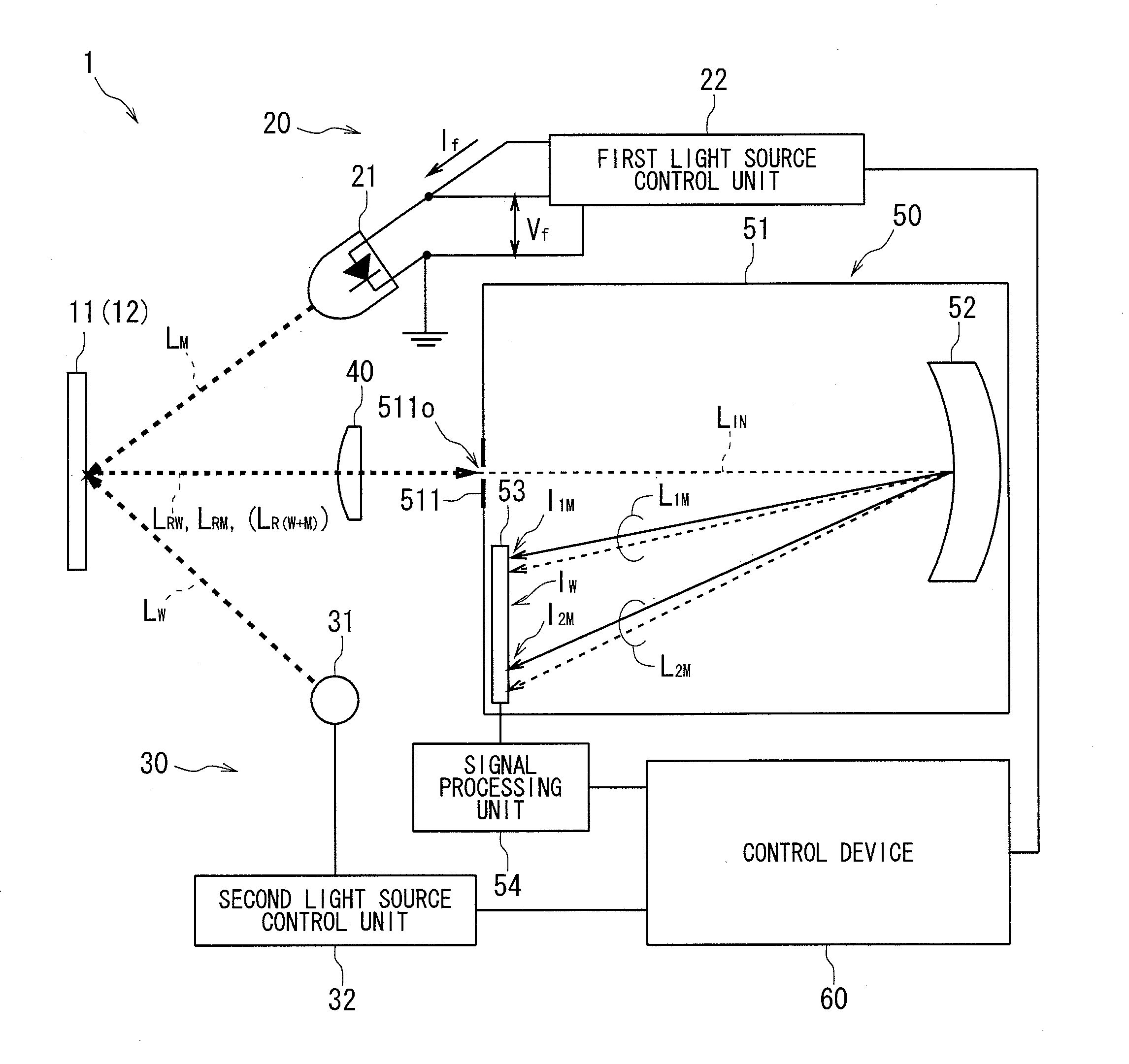
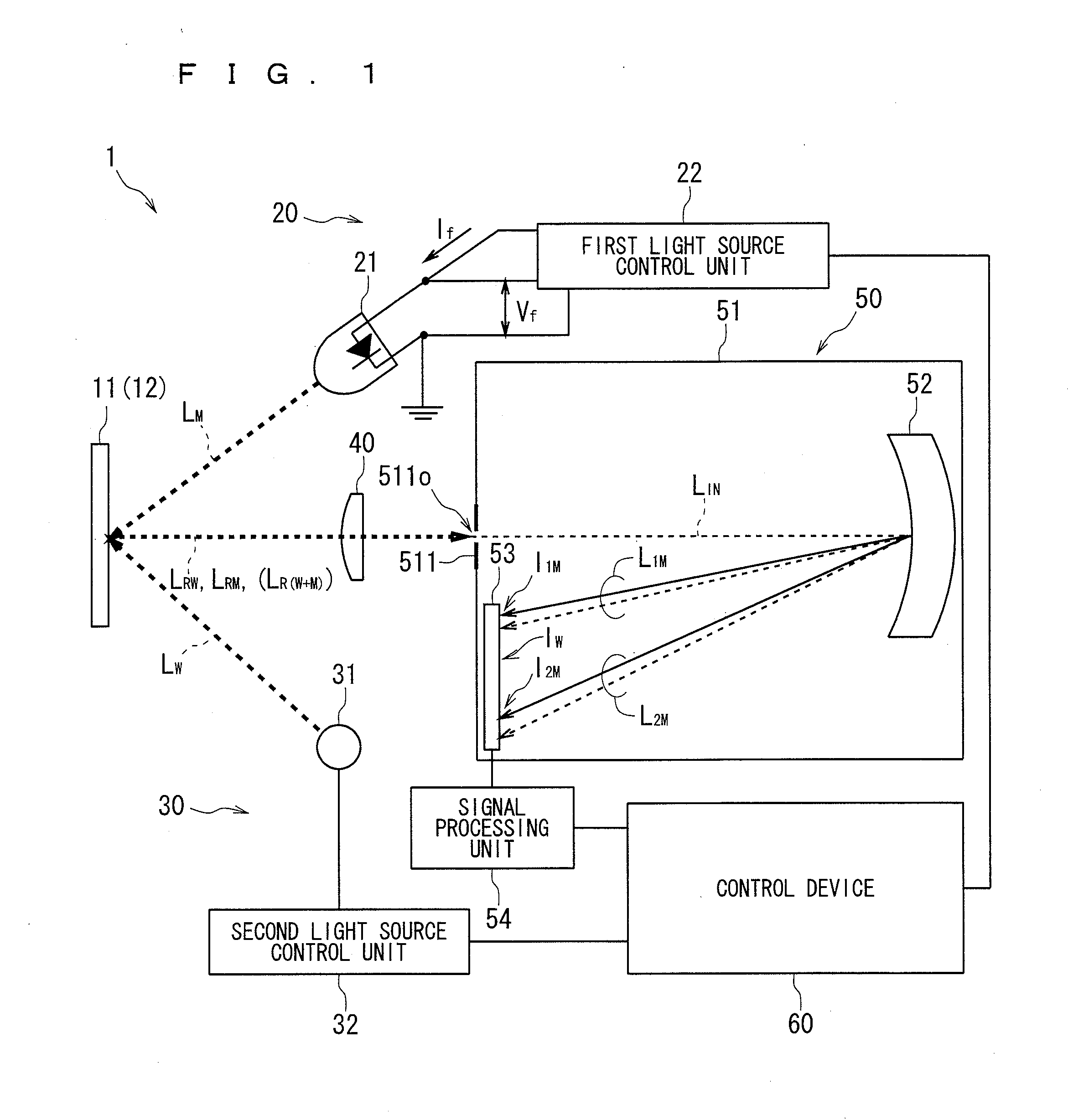
[0061]FIG. 1 is a schematic view showing a configuration of a spectral characteristic measuring device 1 according to one embodiment.

[0062]As shown in FIG. 1, the spectral characteristic measuring device 1 includes a correction illuminating section 20, a measurement illuminating section 30, a light guiding section 40, a spectrometer 50, and a control device 60. In the spectral characteristic measuring device 1, a specimen 11 which is a reference in...


PUM


Abstract

Wavelength information indicating a correspondence relationship between a plurality of light receiving elements of a light receiving unit and wavelengths of pieces of lights is stored. First and second intensity distributions of the light related to first and second dispersion images are acquired based on a signal outputted from each of the light receiving elements when a monochromatic light is passed through a opening of a light shielding body and first and second dispersion images related to primary and secondary diffracted light are formed on the light receiving unit. An estimated intensity distribution of the light related to the second dispersion image is calculated from the first intensity distribution according to a predetermined relational expression. A change amount related to the wavelength information is calculated based on the estimated intensity distribution and the second intensity distribution. The wavelength information is corrected according to the change amount.

Description

TECHNICAL FIELD[0001]The present invention relates to techniques of correcting a device for measuring spectral characteristics, and for example, a technique of correcting a shift in wavelength that occurs in measurement results according to various temporal and thermal changes that may occur in polychromators, and in particular, in a polychromator in which a plastic molded article is used for the main configuring elements.BACKGROUND ART[0002]A polychromator including a light receiving element array in which a great number of light receiving elements are arrayed and a diffraction grating is often used for a measurement device that uses light dispersion such as a spectrophotometer, spectroscopic luminance meter, and the like (also referred to as a spectroscopic system). The diffraction grating may disperse the light to be measured (also referred to as target light to be measured) according to a wavelength. The light receiving array may acquire an electric signal corresponding to an in...

Claims


Application Information

Patent Timeline
Patent Type & Authority Applications(United States)
IPC IPC(8): G01J3/28
CPCG01J3/28G01J3/0297G01J3/18G01J2003/102
Inventor IMURA, KENJI
Owner KONICA MINOLTA INC
Learn More