Annulus to create distinct illumination and imaging apertures for an imaging system

an imaging system and annulus technology, applied in the field of imaging systems, can solve problems such as loss, optical return loss, damage to light sources,

Inactive Publication Date: 2013-12-05
JDS UNIPHASE CORP
View PDF15 Cites 18 Cited by
  • Summary
  • Abstract
  • Description
  • Claims
  • Application Information

AI Technical Summary

Benefits of technology

[0022]a transparent outer ring enabling the first portion of the light to pass from the light source to the angled surface at the second acute angle;

Problems solved by technology

Loss is incurred, whenever a connector is installed on the end of an optical fiber.
The back reflections, known as Optical Return Loss (ORL), will damage the light sources and disrupt the transmitted signal.
Accordingly, an imaging system or microscope used to inspect a PC fiber cannot be used to adequately inspect an APC fiber unless an adaptor is used to position the APC fiber.
But that large NA results in a depth of field too small to form an image.

Method used


Image

  • Annulus to create distinct illumination and imaging apertures for an imaging system
  • Annulus to create distinct illumination and imaging apertures for an imaging system
  • Annulus to create distinct illumination and imaging apertures for an imaging system

Examples


Embodiment Construction

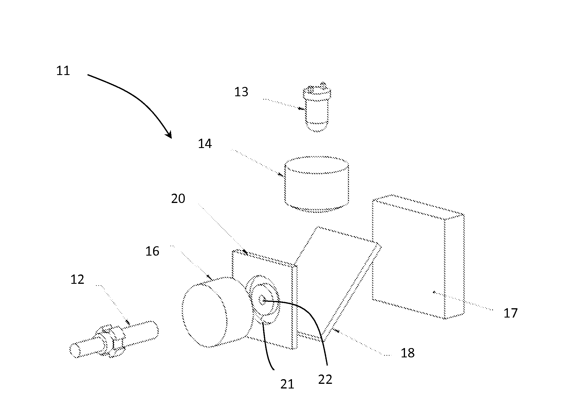
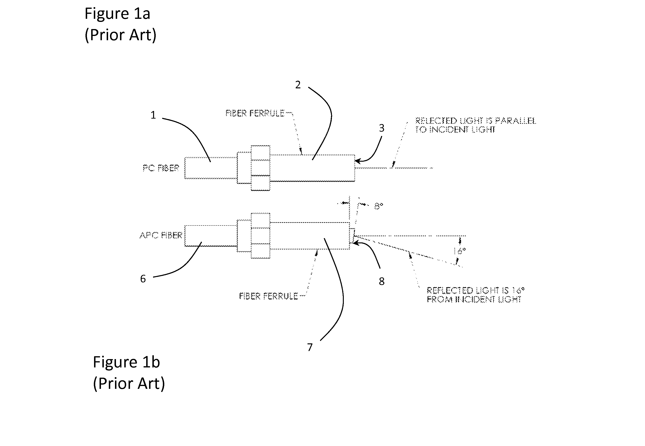
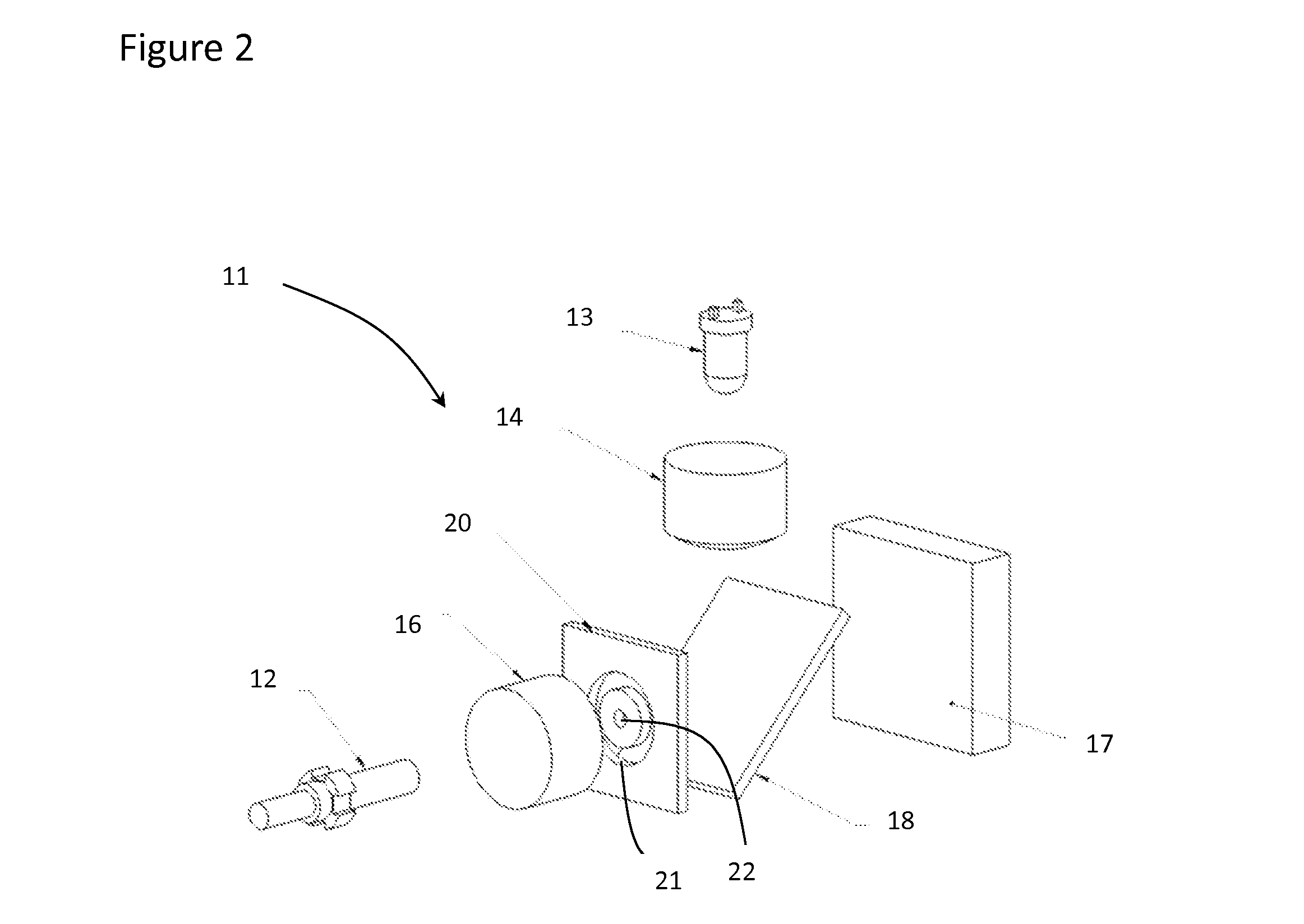
[0034]With reference to FIG. 2, a microscope 11 for examining the ends of optical elements, such the PC fiber 1 and the APC polished optical fiber 6, includes a light source 13 for generating light, a focusing lens 14 for focusing the light on the end face ⅜ of the optical fiber ⅙, and a imaging lens 16 for redirecting the light onto the end face ⅜ of the optical fiber ⅙ and for imaging the light reflected by the end face ⅜ of the optical fiber ⅙ onto a collector 17, e.g. photodetector for a video microscope or a lens for an optical microscope. The lenses 14 and 16 combine to provide lensing for the microscope system, which can include additional lenses at various locations depending on the requirements of the system. The collector 17 is essentially a viewing plane from which an image of the end face of the optical fiber 6 can be viewed or transmitted to a remote location. An eye piece and / or simply a human eye can be positioned at the collector viewing plane 17 to focus the image. ...


PUM


Abstract

An imaging system for viewing both flat and angled surfaces of a test element, such as the end faces of both PC and APC optical fibers. A light source provides light to the angled surface, while lensing directs a portion of the original light to the angled surface at a second acute angle. A collector, e.g. photodetector, lenses or human eye, receives the portion of the light reflected from the angled surface and generates an image thereof. An annulus is provided in the optical path for managing the light. The annulus includes a transparent outer ring enabling the portion of the light to pass from the light source to the surface at the second acute angle; a central transparent section enabling light reflected from the angled surface to pass to the collector along the longitudinal optical axis; and a first light-blocking ring between the outer ring and the central section for blocking excess light from the light source and reflected from the end surface.

Description

CROSS-REFERENCE TO RELATED APPLICATIONS[0001]The present invention claims priority from U.S. Patent Provisional Application No. 61 / 652,659 filed, May 29, 2012, which is incorporated herein by reference.TECHNICAL FIELD[0002]The present invention relates to an imaging system, and in particular to an annulus to block light in the illumination path of an imaging system to enable viewing of both physical contact (PC) and angled physical contact (APC) fiber ends without the need of angled adaptors.BACKGROUND OF THE INVENTION[0003]Loss is incurred, whenever a connector is installed on the end of an optical fiber. A portion of the light lost is reflected directly back down the optical fiber towards the source of the light. The back reflections, known as Optical Return Loss (ORL), will damage the light sources and disrupt the transmitted signal. To minimize loss, the end of the optical fiber is subjected to a variety of polish profiles, depending on the type of fiber and the application.[000...

Claims


Application Information

Patent Timeline
Patent Type & Authority Applications(United States)
IPC IPC(8): G02B27/00
CPCG02B27/00G02B21/0016G02B5/003G02B21/008G01M11/31
Inventor KRIOFSKE, PETERCASSADY, KEVIN G.
Owner JDS UNIPHASE CORP
Why Eureka
Try Eureka