Air compressor unit

a compressor and air technology, applied in the direction of pumps, mechanical equipment, liquid fuel engines, etc., can solve the problems of high construction complexity of compressors of this type, high precision machining and assembly of components, and cumbersomeness

Inactive Publication Date: 2013-12-05
F I A C
View PDF6 Cites 12 Cited by
  • Summary
  • Abstract
  • Description
  • Claims
  • Application Information

AI Technical Summary

Benefits of technology

[0014]This invention therefore has for an aim to overcome the above mentioned drawbacks by providing a compact, high-efficiency multi-cylinder air compressor unit.

Problems solved by technology

The development of multi-cylinder configurations essentially translates as production of compressors which are somewhat cumbersome and which have complex parts for coordinating the operation of the multiple cylinders.
Compressors of this kind are considerably complicated in construction and require high precision machining and assembling of components, with extremely tight tolerances.
Moreover, the increased number of cylinders has given rise to problems, as yet unsolved, in cooling the cylinders and the air supplied by them.
In other words, the main drawbacks of prior art multi-cylinder compressors are due to their constructional complexity and the size and weight of their mechanical components.
This complexity involves high production costs which constitute a further drawback of the prior art compressors.

Method used


Image

  • Air compressor unit
  • Air compressor unit
  • Air compressor unit

Examples


Embodiment Construction

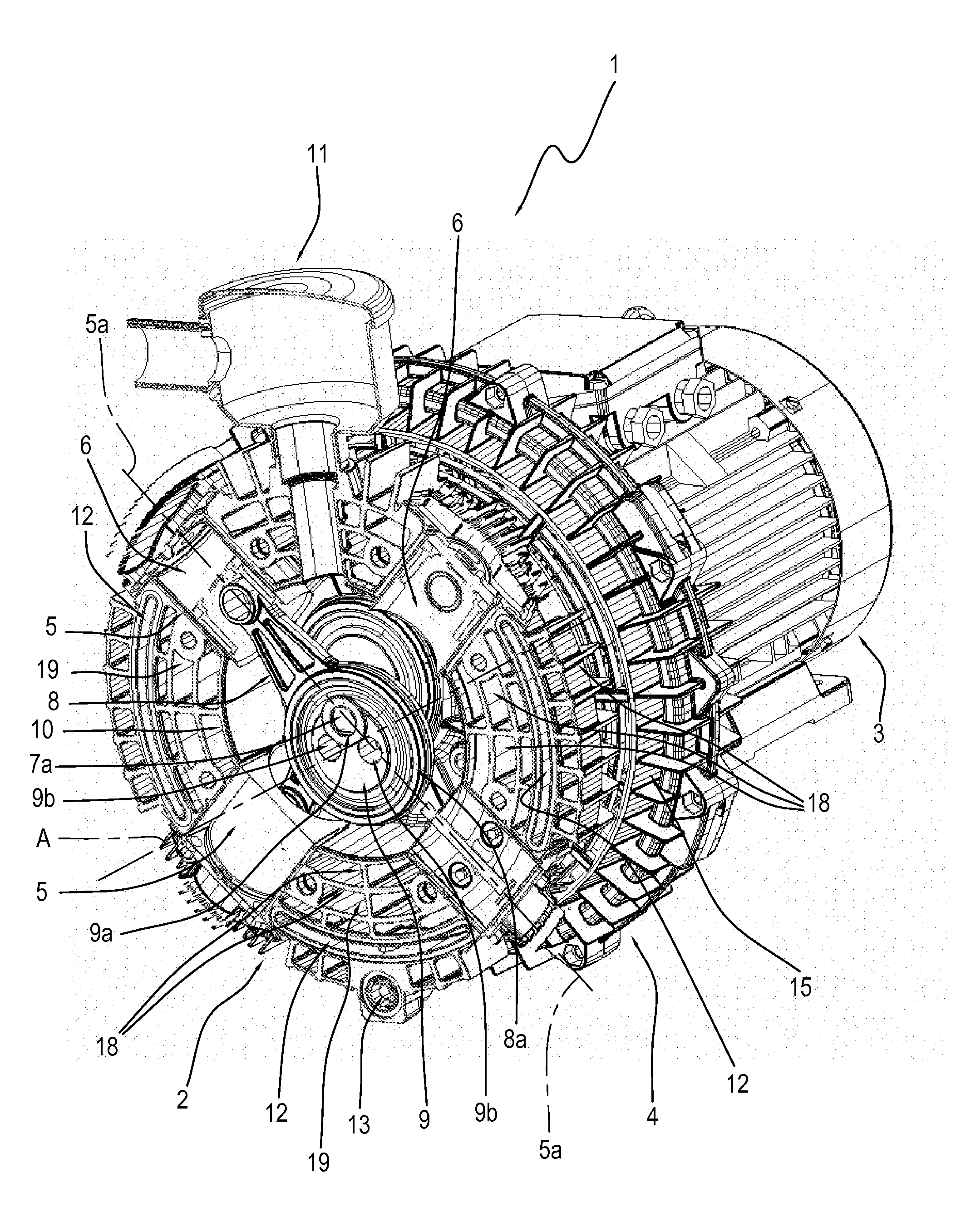
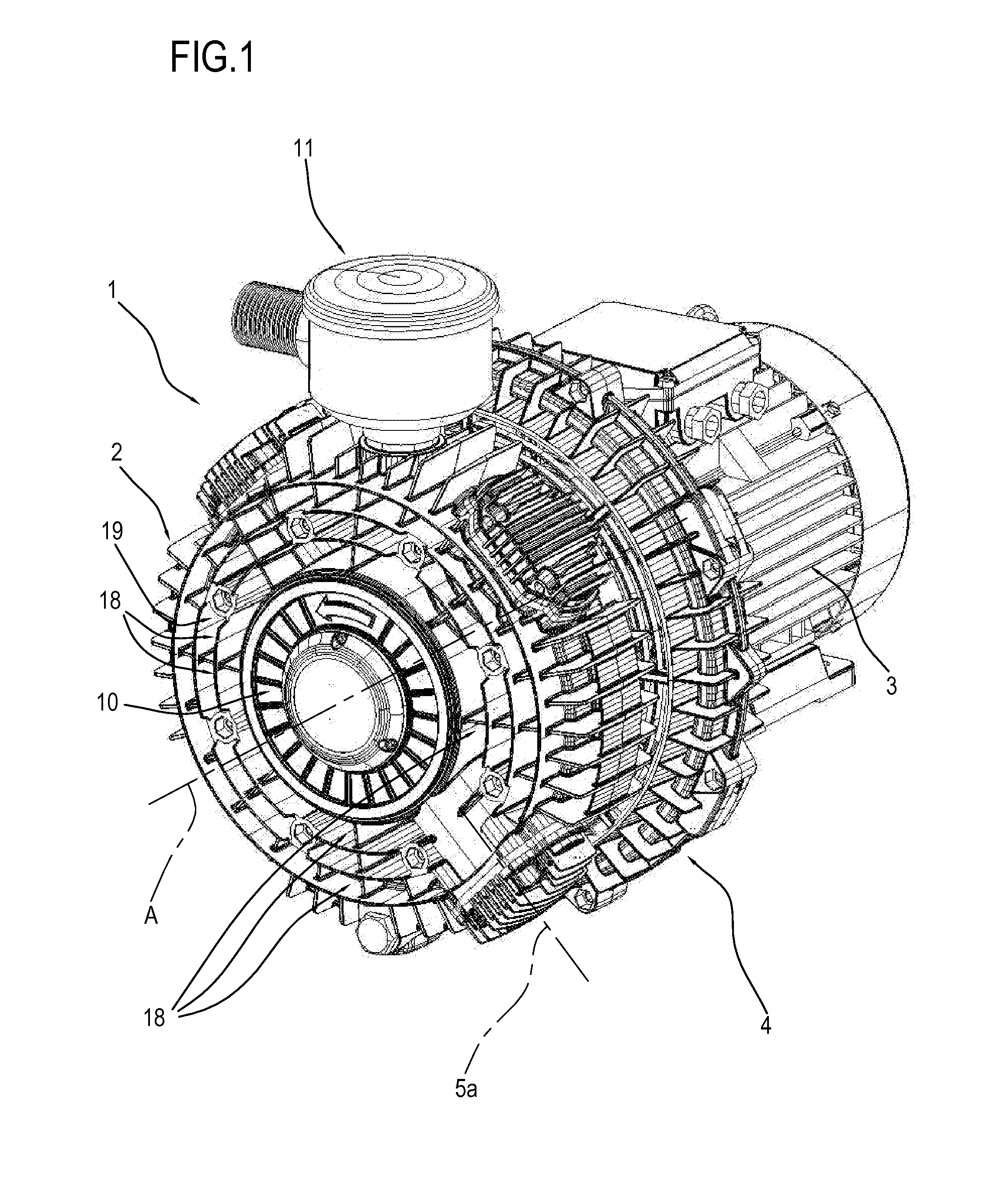
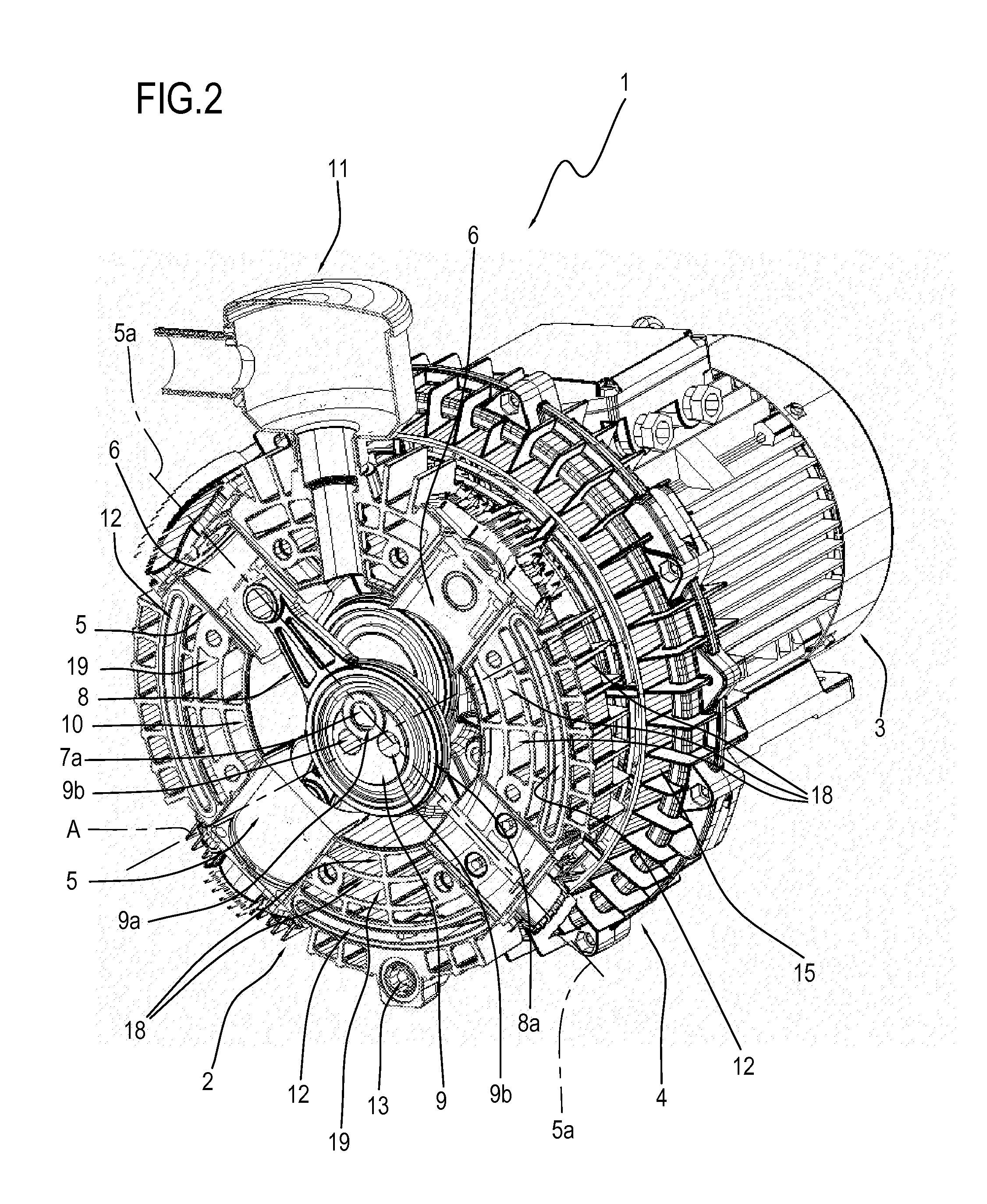
[0023]In the accompanying drawings, the reference numeral 1 denotes a volumetric reciprocating compressor for compressing air for use preferably by pneumatic tools.

[0024]As clearly illustrated in FIGS. 1 and 2, the compressor 1 comprises an air compressing unit 2, a motor 3 for driving the compressing unit 2 and a cooling unit 4 by which the compressed air from the unit 2 is cooled.

[0025]As illustrated in FIGS. 2 and 3, the air compressing unit 2 comprises a plurality of cylinders 5 (four in the embodiment illustrated), within which respective reciprocating pistons 6 are received.

[0026]The motor 3, which is advantageously an electric motor, has a shaft 7 which rotates about a respective axis of rotation A.

[0027]As described in detail below, the rotating shaft 7 protruding from the motor 3 drives both the cooling unit 4 and the compressing unit 2.

[0028]Each piston 6 is kinematically connected to the shaft 7 by a respective con rod 8 and a crank lever member 9.

[0029]The crank lever me...


PUM


Abstract

A volumetric reciprocating compressor comprises an air compressing unit equipped with a plurality of cylinders adapted to receive reciprocating pistons, a motor for driving the compressing unit and having a shaft which rotates about a respective axis of rotation, a cooling unit comprising a fan assembly driven by the rotating shaft to produce an air flow for cooling the compressed air in the unit, the cylinders being located inside an axisymmetric housing casing and being angularly spaced from each other.

Description

[0001]This application claims priority to Italian Patent Application BO2012A000308 filed Jun. 5, 2012, the entirety of which is incorporated by reference herein.BACKGROUND OF THE INVENTION[0002]This invention relates to an air compressor unit.[0003]More specifically, the invention relates to a volumetric reciprocating air compressor.[0004]The air compressor unit of the invention can be used in any situation where a supply of compressed air is required.[0005]in many technical activities, pneumatic tools are used because they are very practical and robust. Such activities include, for example, the application of rivets in metal sheeting and nails in wood, and the loosening and tightening of vehicle wheel bolts.[0006]Especially in professional applications, tools of his kind are required to attain higher and higher performance levels.[0007]Obviously, increasing the performance level normally corresponds to an increase in the overall dimensions of the tools and of the compressor units w...

Claims


Application Information

Patent Timeline
Patent Type & Authority Applications(United States)
IPC IPC(8): F04B53/08
CPCF04B53/08F04B39/12F04B39/066F04B27/04
Inventor LUCCHI, FABIO
Owner F I A C
Why Eureka
Try Eureka