Wide-band optical coupler

a wide-band, optical coupler technology, applied in the field of low-wavelengthdependent optical couplers, can solve the problems of increasing the manufacturing cost, reducing the yield, increasing the polarization dependent loss (pdl), etc., and achieves the effects of low polarization dependence, low yield, and low manufacturing cos

Inactive Publication Date: 2013-12-12
FURUKAWA ELECTRIC CO LTD
View PDF2 Cites 0 Cited by
  • Summary
  • Abstract
  • Description
  • Claims
  • Application Information

AI Technical Summary

Benefits of technology

[0013]In the present invention, because the three directional couplers have the same pitch and length, the optical coupler is less susceptible to the manufacturing errors, i.e., achieves high process stability. Moreover, because the two delay paths can give the two different phase differences between the split optical signals, the optical coupler can be configured to achieve both of low polarization dependence and low wavelength dependence. Thus, the optical coupler according to the present invention is capable of performing low-wavelength-dependent optical signal split in a wide band while realizing high process stability and low PDL.

Problems solved by technology

Hence, the optical coupler is susceptible to manufacturing errors, which causes a problem of reducing the yield and increasing the manufacturing cost.
This causes a problem of an increase in the polarization dependent loss (PDL) because the longer coupling length increases the polarization dependence of the coupling efficiency.
Accordingly, due to a trade-off between high process stability and low polarization dependence, the conventional configuration shown in FIG. 6 has difficulty achieving a non-wavelength-dependent optical coupler capable of concurrently achieving these even if the designed values of the constituents are optimized.

Method used


Image

  • Wide-band optical coupler
  • Wide-band optical coupler
  • Wide-band optical coupler

Examples


embodiment

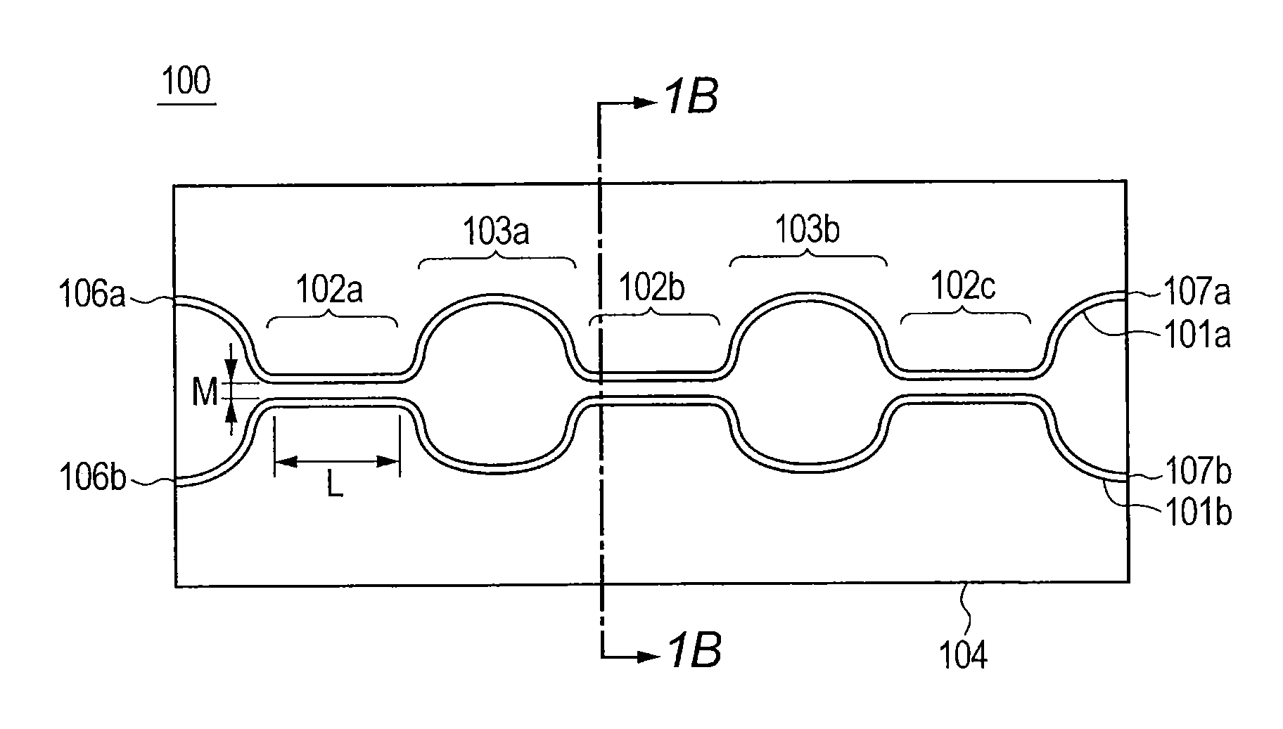
[0025]FIG. 1A shows a schematic diagram of an optical coupler 100 according to the embodiment. FIG. 1B shows a cross-sectional view of the optical coupler 100 taken along the 1B-1B line. The optical coupler 100 includes: a substrate 104; and a cladding layer being formed on the substrate 104 and having two waveguides 101a, 101b inside. The waveguides 101a, 101b are bent as shown in FIG. 1A to form three directional couplers 102a, 102b, 102c and two delay paths 103a, 103b. Specifically, the directional couplers 102a, 102b, 102c for coupling together two optical signals travelling through the respective waveguides 101a, 101b are each formed by bringing portions of the waveguides 101a, 101b close to each other in parallel. Moreover, the delay paths 103a, 103b for giving an optical path difference to the waveguides 101a, 101b are each formed by bringing portions of the waveguides 101a, 101b away from each other. The delay path 103a is provided between the directional coupler 102a and th...

example

[0061]An optical coupler 100 according to the present invention was manufactured and its split operation was checked. The manufacturing conditions were as follows.

[0062]Substrate: Quartz-based PLC

[0063]Relative refractive index difference: 0.4%

[0064]Width of each waveguide: 7.0 μ

[0065]Thickness of each waveguide: 7.0 μ

[0066]Pitch M: 10.8 μ

[0067]Coupling portion length L: 290 μ

[0068]Optical path difference ΔL1: −0.01 μ(phase difference: about −3.6 degrees)

[0069]Optical path difference ΔL2: 0.315 μ(phase difference: about 113 degrees)

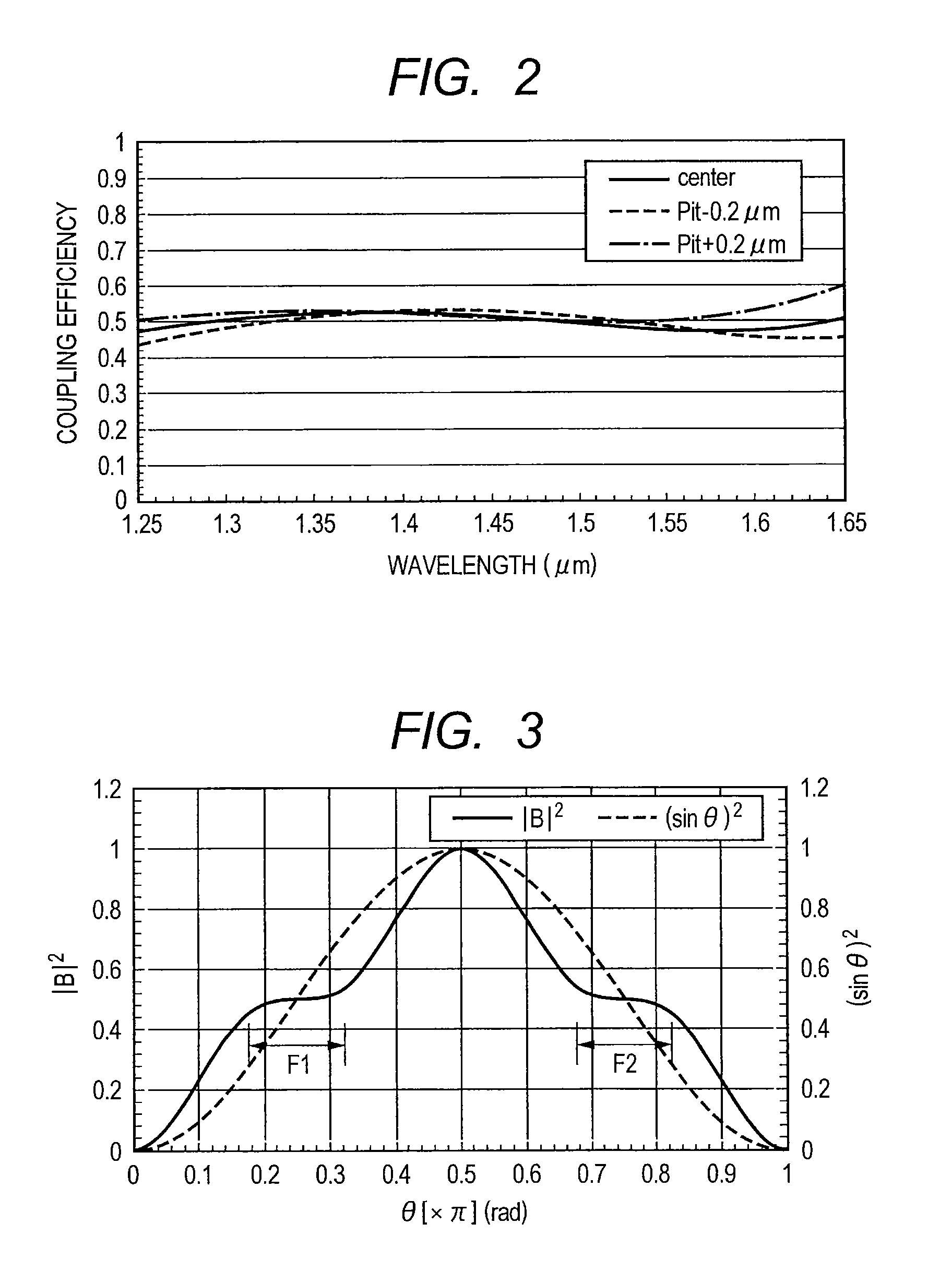
[0070]FIG. 4A shows a graph representing a designed value for the coupling efficiency of each directional coupler included in the optical coupler 100 according to the example. In FIG. 4A, the horizontal axis indicates the wavelength and the vertical axis indicates the coupling efficiency. The solid line indicates the TM mode and the broken line indicates the TE mode. As can be learned from FIG. 4A, each directional coupler is designed in such a way that i...


PUM


Abstract

The present invention aims to provide a low-wavelength-dependent optical coupler capable of concurrently achieving high process stability and low polarization dependence. An optical coupler 100 according to an embodiment includes a cladding layer 105 being formed on a substrate 104 and having two waveguides 101a, 101b inside. Three directional couplers 102a, 102b, 102c are each formed by bringing portions of the two waveguides close to each other in parallel, and the two delay paths 103a, 103b are each formed to give an optical path difference between the two waveguides. The delay path 103a is provided between the directional couplers 102a and 102b, and the delay path 103b is provided between the directional couplers 102b and 102c. The three directional couplers have the same coupling characteristic, and the two delay paths have different optical path differences from each other.

Description

CROSS-REFERENCE TO RELATED APPLICATIONS[0001]This application is a continuation application of International Application No. PCT / JP2012 / 008038, filed Dec. 17, 2012, which claims the benefit of Japanese Patent Application No. 2012-092260, filed Apr. 13, 2012. The contents of the aforementioned applications are incorporated herein by reference in their entireties.TECHNICAL FIELD[0002]The present invention relates to a low-wavelength-dependent optical coupler operating in a wide band.BACKGROUND ART[0003]In response to recent demand for higher capacity communications, optical fibers have been laid in broader areas. In an optical fiber network (especially an access network), a 2×N optical splitter is used to provide a one-to-multiple optical fiber connection. A 2×2 optical coupler (hereinafter simply called an optical coupler) used for a 2×N optical splitter is required to operate without wavelength dependence because it needs to carry out an operation of splitting an optical signal into...

Claims


Application Information

Patent Timeline
Patent Type & Authority Applications(United States)
IPC IPC(8): G02B6/28
CPCG02B6/2861G02B6/125G02B6/29355
Inventor NARA, KAZUTAKA
Owner FURUKAWA ELECTRIC CO LTD
Why Eureka
Try Eureka