Passage channel for a turbomachine and turbomachine

a technology of passage channel and turbomachine, which is applied in the direction of motors, air transportation, climate sustainability, etc., can solve the problems of high noise development, heavy secondary flows, energy transmission losses, etc., and achieve the effects of minimizing energy transmission losses, improving inflow, and high degree of efficiency

a technology of passage channel and turbomachine, which is applied in the direction of motors, air transportation, climate sustainability, etc., can solve the problems of high noise development, heavy secondary flows, energy transmission losses, etc., and achieve the effects of minimizing energy transmission losses, improving inflow, and high degree of efficiency

US20130330180A1Inactive Publication Date: 2013-12-12MTU AERO ENGINES GMBH

Image

  • Passage channel for a turbomachine and turbomachine
  • Passage channel for a turbomachine and turbomachine
  • Passage channel for a turbomachine and turbomachine

Examples


Embodiment Construction

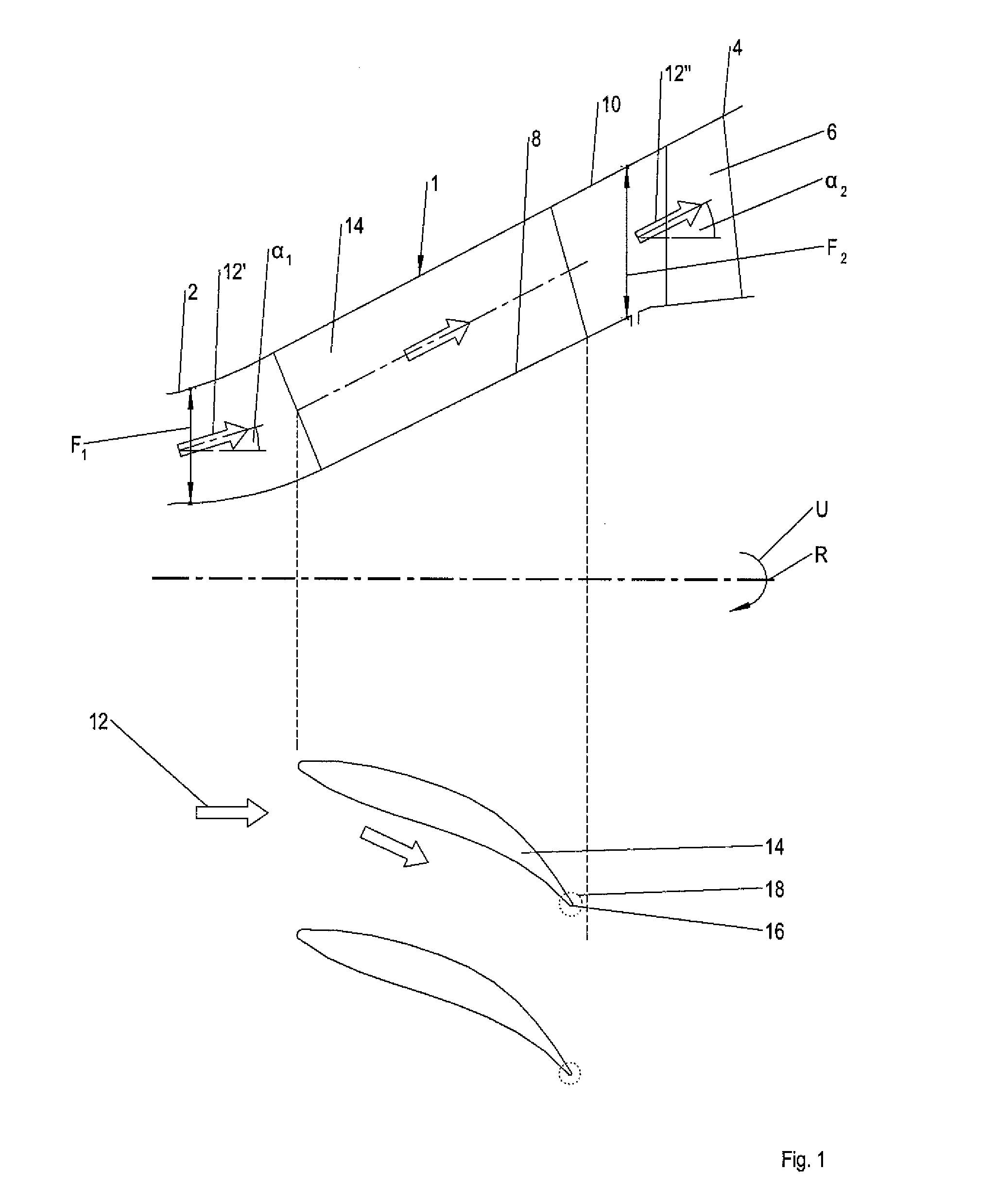
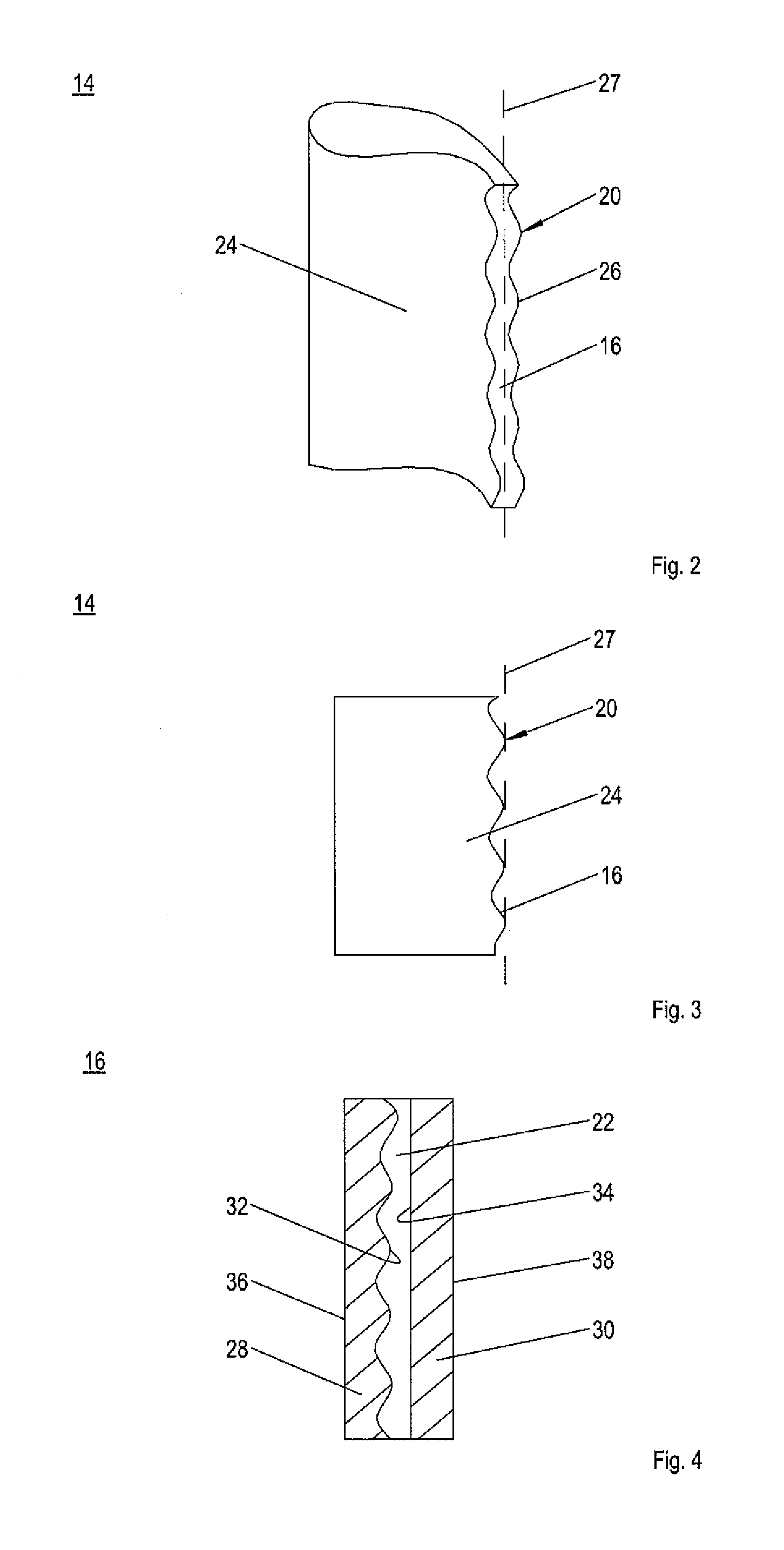
[0033]In the figures, identical structural elements are denoted with the same reference numeral, for the sake of clarity only one element being or may be provided with a reference numeral in the case of multiple identical elements in one figure.

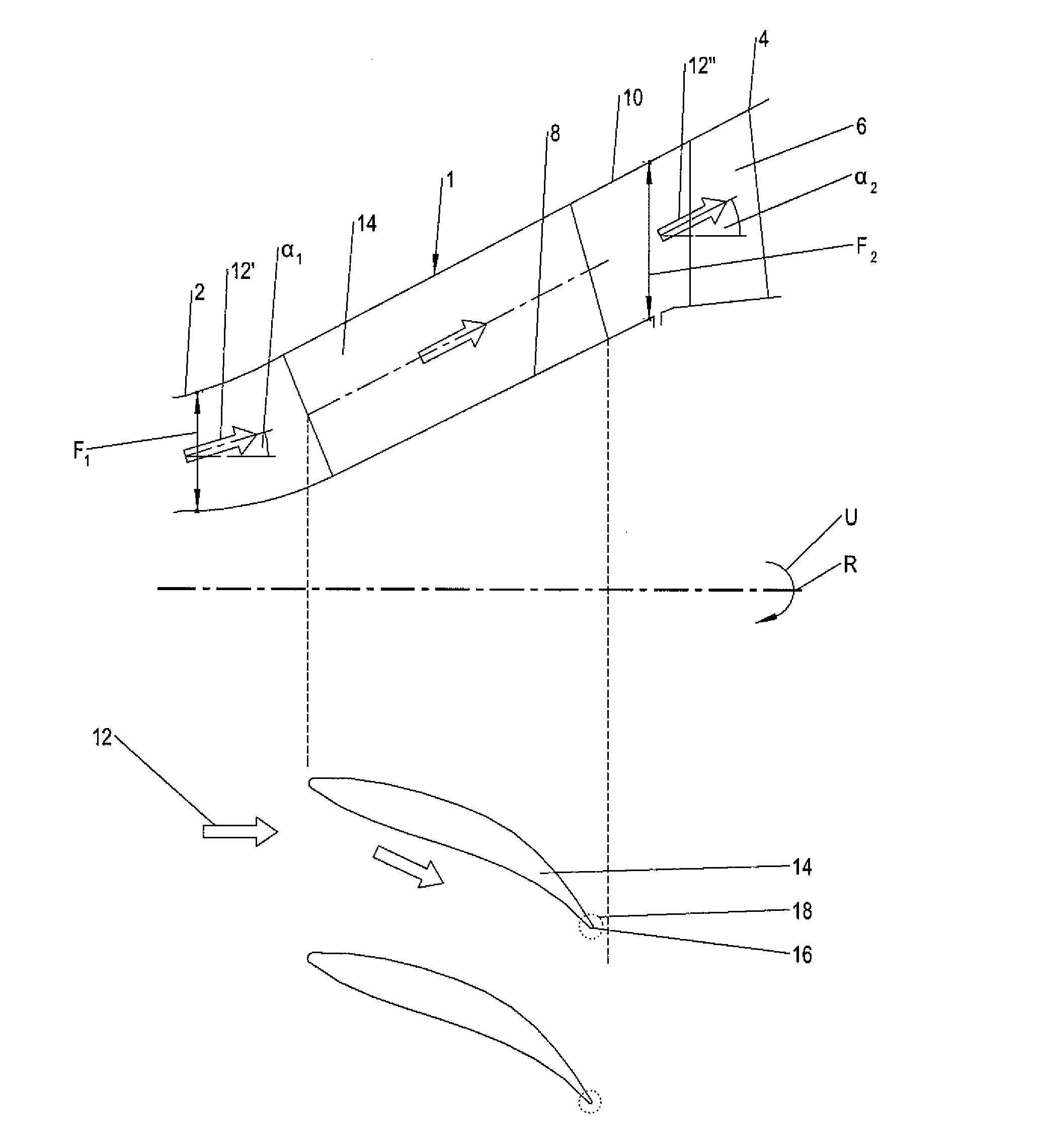
[0034]FIG. 1 shows an example of a transition duct 1 between a high pressure turbine 2 and a low-pressure turbine 4 of an axial turbomachine, such as an aircraft engine, in an axial half section or meridian section (upper part of the figure) as well as in a planar developed view or in a profile section (lower part of the figure).

[0035]Transition duct 1 is mounted in a stationary manner in a turbine housing, while high pressure turbine 2 and low pressure turbine 4 each have moving blade rows 6 which rotate around a rotation axis or turbine axis R in rotation direction U. Transition duct 1 encompasses rotation axis R and has an annular flow cross section. It has a radially inner duct wall 8, a radially outer duct wall 10 and a high pressure tur...


PUM


Abstract

A transition duct for a turbomachine, in particular an aircraft engine, for forming a flow channel between an upstream flow cross section and a downstream flow cross section, including supporting ribs which extend between a radially inner duct wall and a radially outer duct wall and each of which has a profile for deflecting a flow from an inlet area to an outlet area of the transition duct, the supporting ribs each having a profile variation in the area of their trailing edge and / or at least one blow-out opening for blowing out a fluid; also disclosed is a turbomachine having a transition duct of this type.

Description

[0001]This claims the benefit of European Patent Application EP 12170498.5, filed Jun. 1, 2012 and hereby incorporated by reference herein.[0002]The present invention relates to a transition duct for a turbomachine as well as a turbomachine.BACKGROUND[0003]A transition or deflecting duct in an axial turbomachine, such as an aircraft engine, conducts a main flow from an upstream flow cross section to a radially offset flow cross section. The transition duct usually has an annular cross section and is situated, for example, between a high pressure turbine and a low pressure turbine (turning mid turbine frame—TMTF). In a three-part design of a turbine, the transition duct may also be situated between a high pressure turbine and an intermediate pressure turbine as well as between the intermediate pressure turbine and a low pressure turbine. In compressors, a transition duct may similarly conduct the flow from an upstream flow cross section to a downstream flow cross section and be situa...

Claims


Application Information

Patent Timeline
12 Dec 2013
Publication
US20130330180A1
IPC
F04D29/00
CPC
F04D29/00; F01D5/145; F01D5/186; F01D9/023; F01D9/06; F01D9/065; F05D2250/184; Y02T50/60
Inventors
GUENDOGDU, YAVUZ; ENGEL, KARL