Method for producing the tooth shape of the inner and outer ring of an annular gear machine and toothed ring produced by means of said method

a technology inner and outer ring, which is applied in the direction of engine lubrication, rotary piston engine, portability lifting, etc., can solve the problems of limited efficiency and flow conditions inability to achieve a major goal of annular gear machine, and inability to define special geometries of toothing schemes with undercuts or reduce hertzian pressure, etc., to achieve high efficiency, improve delivery performance, and high operating speed

Active Publication Date: 2013-12-12
NIDEC GPM GMBH
View PDF3 Cites 9 Cited by
  • Summary
  • Abstract
  • Description
  • Claims
  • Application Information

AI Technical Summary

Benefits of technology

[0032]Since, with the method of the invention, the complete tooth shape contour of the inner and the outer ring is generated in each run-through, starting from a given starting geometry of a first annular gear, the resulting tooth shape contours or geometries on the one hand and the roll-off or sliding behavior of the toothing of the two annular gears on the other hand can undergo an evaluation, i.e., a comparison with a quality criterion. If the quality criteria are properly chosen, one can also generate gerotor toothings with relatively large eccentricity values in this way. Obeying the above explained condition of motion assures a harmonic movement sequence between inner and outer toothing, as well as a kinematically harmonic running with high efficiency.
[0033]Especially when the annular gear machine is used as an annular gear pump, the method of the invention enables a dimensioning with large eccentricities, so that streamlined delivery chambers can be configured to improve the delivery performance at high operating speed. The method is basically suitable for the most diverse tooth shapes, numbers of teeth, eccentricities and pitch circle radii. Furthermore, it is advantageous that no special steps need to be taken to adapt the ends of individual curve segments which are customarily used for the description of the tooth shape to mathematical requirements of the description being used in their transitional behavior. Instead, the curves result entirely from the explained process of optimizing the tooth shape. The mathematical description of the resulting geometry is done preferably by splines of higher order, and sufficient accuracy for practical requirements can usually be attained already with splines of third order.
[0034]According to one preferred embodiment, several quality criteria can be established, which are checked in parallel for their fulfillment when evaluating several generated tooth shape contours. For example, besides a minimum volume being delivered, one can also specify the force relations to be obeyed between the tooth flanks of the meshing teeth. In this way, it is possible to reduce the Hertzian pressure, for example, by increasing the local contact radii (arcs).

Problems solved by technology

With the method proposed there, however, it is not possible to achieve a major goal of an annular gear machine, namely, to configure a geometrically closed delivery cell at all times between the two annular gears in the course of the motion, or if so only in very narrow limits.
The definition of special geometries of toothing schemes with undercuts or to reduce the Hertzian pressure is hardly possible, if at all, due to being limited to describing the tooth shape by means of a defined number of circular arcs.
However, studies have shown that the tooth shapes which can be generated in this way lead to limitations in regard to efficiency and flow conditions in the annular gear machine.
Another drawback is the rigid definition of the root fillet, which has limiting effect on the configuration of a dirt catching space, for example.
This method is based on the use of variance functions, but it requires time-consuming calculations and design steps and can lead to dimensioning problems, especially when undercuts are present.

Method used


Image

  • Method for producing the tooth shape of the inner and outer ring of an annular gear machine and toothed ring produced by means of said method
  • Method for producing the tooth shape of the inner and outer ring of an annular gear machine and toothed ring produced by means of said method
  • Method for producing the tooth shape of the inner and outer ring of an annular gear machine and toothed ring produced by means of said method

Examples


Embodiment Construction

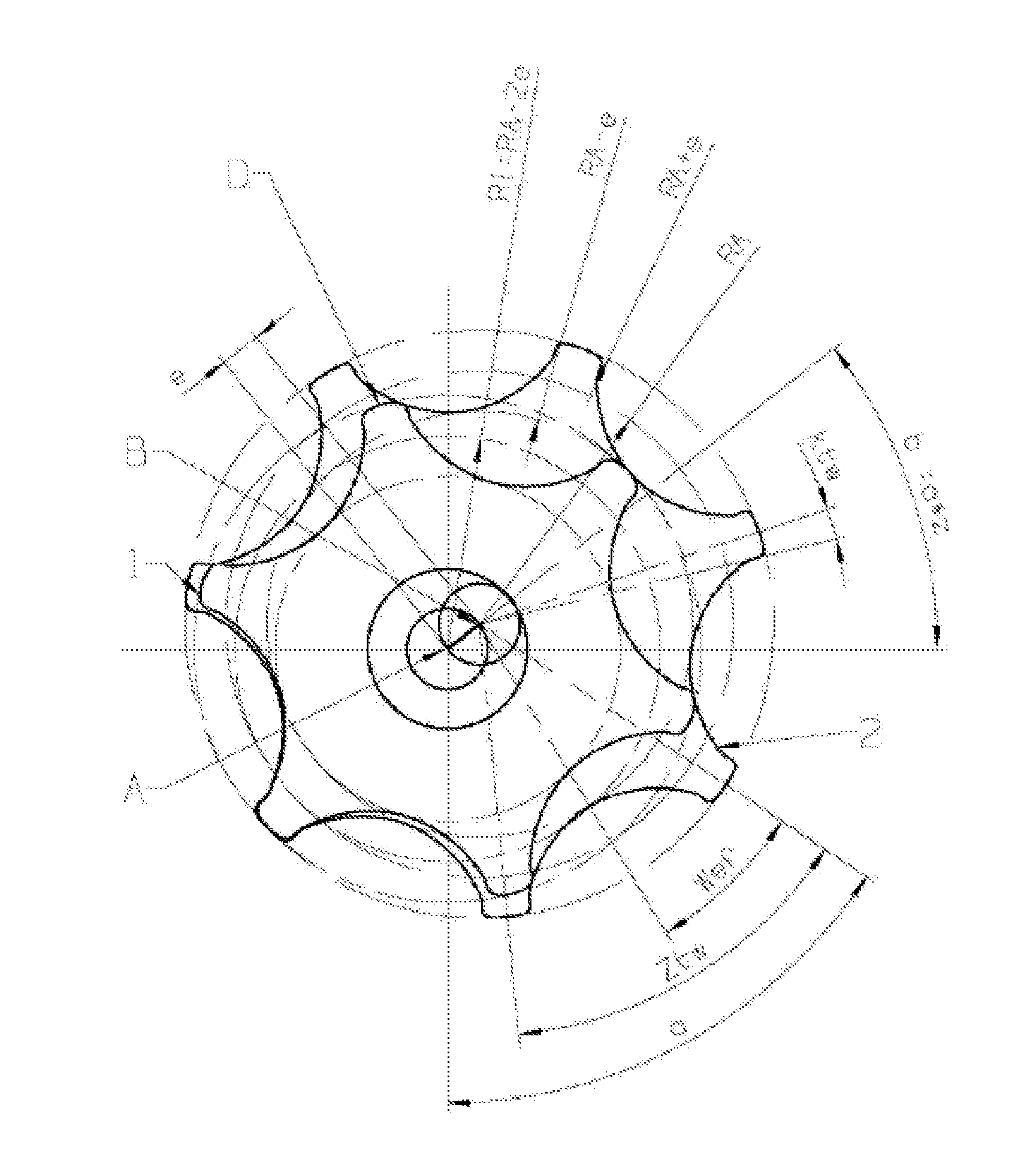
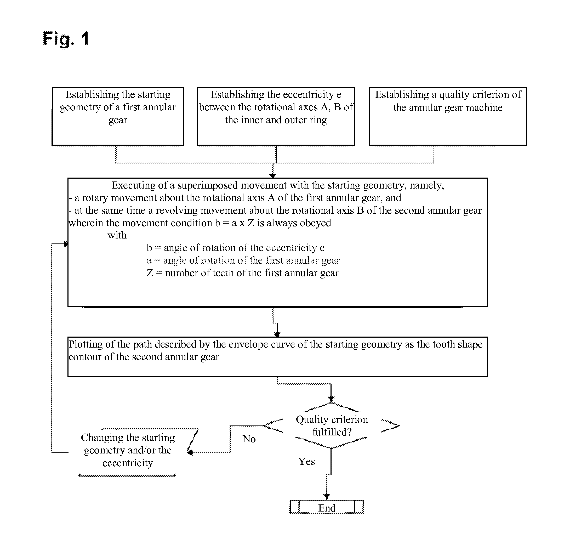
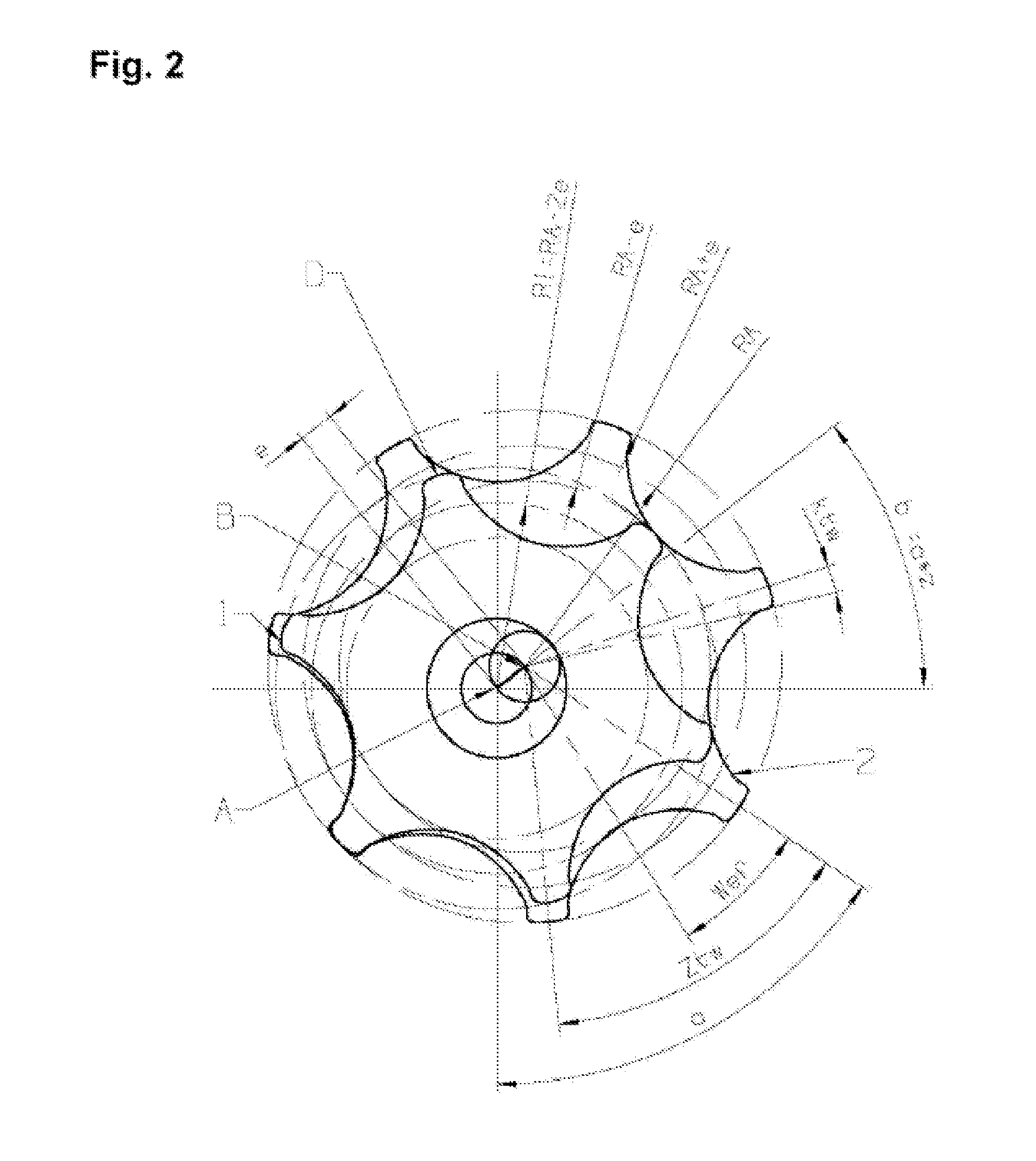
[0042]The following description of essential and preferred steps of the method of the invention makes reference to FIG. 1, in which the sequence of the method is summarized, and at the same time referring to FIGS. 2 and 3, in which important geometrical features of the teeth of an annular gear machine are shown.

[0043]Basically, the method of the invention is aimed at generating tooth shapes of an annular gear machine, wherein the annular gear machine has an inner ring 1 with an outer toothing and an outer ring 2 with an inner toothing as principal elements. In a typical application, the inner ring can be mounted on a power take-off shaft of a drive assembly, while the outer ring 2 is mounted and able to turn in a housing (not shown). In operation, the inner ring 1 rotates about a first rotational axis A, while the outer ring 2 can turn about a second rotational axis B. The rotational axes A, B are set off from each other or spaced apart by the amount of an eccentricity e. Furthermor...


PUM

PropertyMeasurementUnit
tooth shapeaaaaaaaaaa
angle of rotationaaaaaaaaaa
angleaaaaaaaaaa

Abstract

In producing tooth shapes of two toothed rings of an annular gear machine, a starting geometry of a first toothed ring, at least one quality criterion of the annular gear machine, and a desired eccentricity between rotational axes of the two toothed rings are defined. A motion is performed with the starting geometry that performs a rotational motion about its rotational axis and a revolving motion about the rotational axis of the second toothed ring. The rotational and revolving motions are coupled so the rotational angle of the eccentricity equals the product of the rotational angle and tooth count of the first toothed ring. A tooth shape contour of the second toothed ring is generated by recording the path described by the envelope of the starting geometry. If the defined quality criterion is not met, the previously used starting geometry and/or the defined eccentricity is changed and steps are repeated.

Description

FIELD OF THE INVENTION[0001]The present invention concerns a method for producing the tooth shapes of both the inner ring and the outer ring of an annular gear machine (also known as a gerotor), especially an annular gear pump. Furthermore, the invention concerns an annular gear of an annular gear machine that has such a toothing.BACKGROUND OF THE INVENTION[0002]Annular gear machines (gerotor machines) possess an inner ring and an outer ring, each of them provided with teeth and tooth gaps regularly distributed about the circumference. The rotational axes of the inner ring and the outer ring are eccentrically set off from each other. The inner ring usually has exactly one tooth less than there are tooth gaps provided at the inner toothing of the outer ring. Annular gear machines today are often used as annular gear pumps, for example, in vehicles as the main pump of the internal combustion engine. The displacement space formed by tooth gaps and housing walls changes with the rotatio...

Claims


Application Information

Patent Timeline
Patent Type & Authority Applications(United States)
IPC IPC(8): F04C2/08F16H55/08
CPCF04C2/084F16H55/08F04C2/102F16H57/08F16H2057/0087G06F30/00Y10T29/49242F04C2/086F04C18/084
Inventor BLECHSCHMIDT, ANDREAS
Owner NIDEC GPM GMBH
Why Eureka
Try Eureka