
Glass, in particular solder glass or fusible glass

a technology of solder glass and fusible glass, which is applied in the field of solder glass or fusible glass, can solve the problems of low temperature resistance, high alkali content, and lead content of solder glass, and achieve the effect of sufficient chemical stability and high temperature resistan

Inactive Publication Date: 2013-12-12
SCHOTT AG
View PDF4 Cites 8 Cited by
  • Summary
  • Abstract
  • Description
  • Claims
  • Application Information

AI Technical Summary

Benefits of technology

The patent text describes a new glass composition that has high stability and can be used as a solder glass. This glass composition contains up to 45 mol-% of lithium, which prevents crystallization during a sintering process. The glass composition is also stable in the presence of non-aqueous battery electrolytes. The technical effect of this patent text is that it provides a reliable and stable material for use in battery feed-throughs.

Problems solved by technology

A disadvantage of the solder glass according to U.S. Pat. No. 5,262,364 is that the solder glass contains lead, in other words PbO as well as a relatively high amount of Na2O.
Even though these glasses contain little or no lead, they do have very high alkali content.
In particular in the use of storage devices, such as lithium-ion accumulators in the automobile industry, a multitude of problems such as corrosion resistance, stability in accidents and vibration resistance must be solved.
An additional problem is the hermetic seal of the battery, for example the lithium-ion battery over an extended period of time.
The hermetic seal may, for example, be compromised by leakage in the area of the electrodes of the battery or respectively the electrode feed-through of the battery.
The seal may for example be compromised by a battery short circuit or temperature changes resulting in a shortened life span.
An additional problem with battery feed-throughs is the instability against aggressive battery electrolytes, in particular non-aqueous electrolytes as are used, for example in lithium-ion accumulators.
A disadvantage of the synthetic material insulation is the limited temperature resistance, the uncertain hermetic seal over the service life and the limited chemical stability in regard to the battery electrolytes.

Method used


Image

  • Glass, in particular solder glass or fusible glass
  • Glass, in particular solder glass or fusible glass

Examples


Embodiment Construction

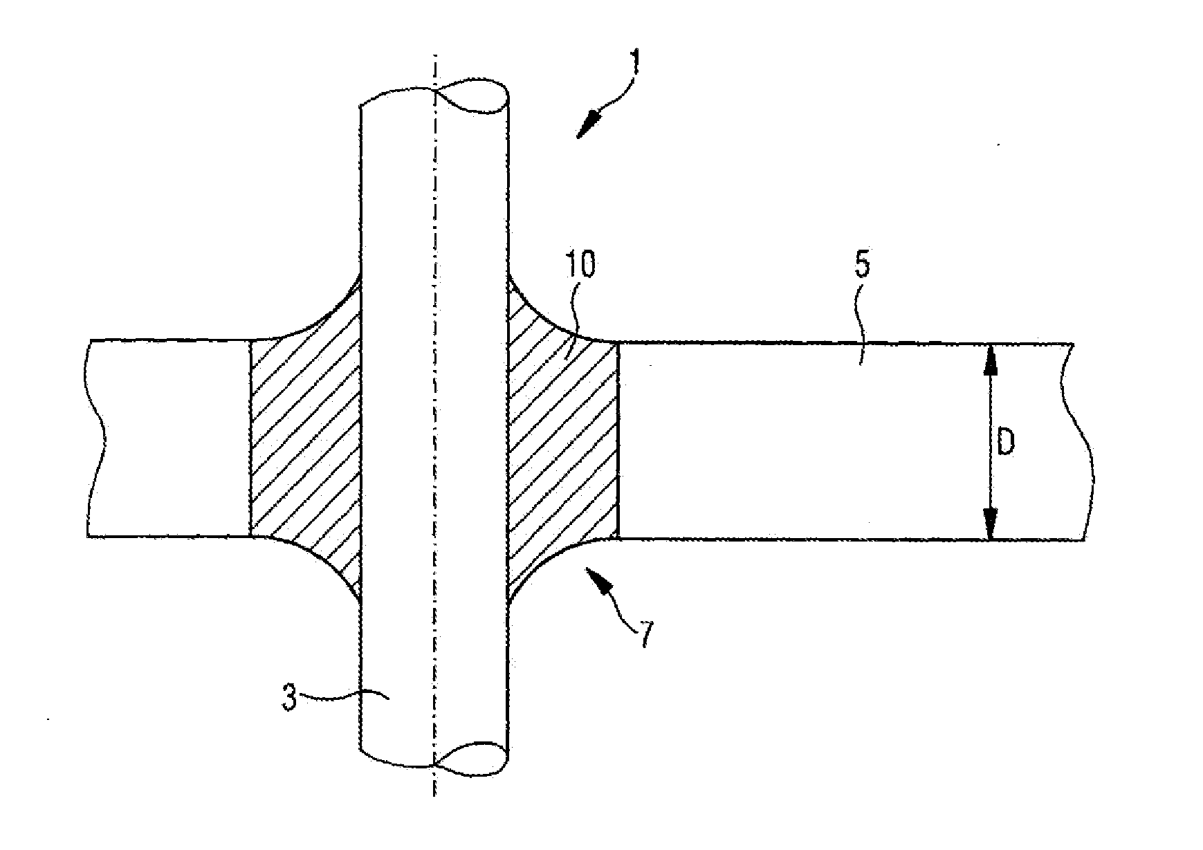
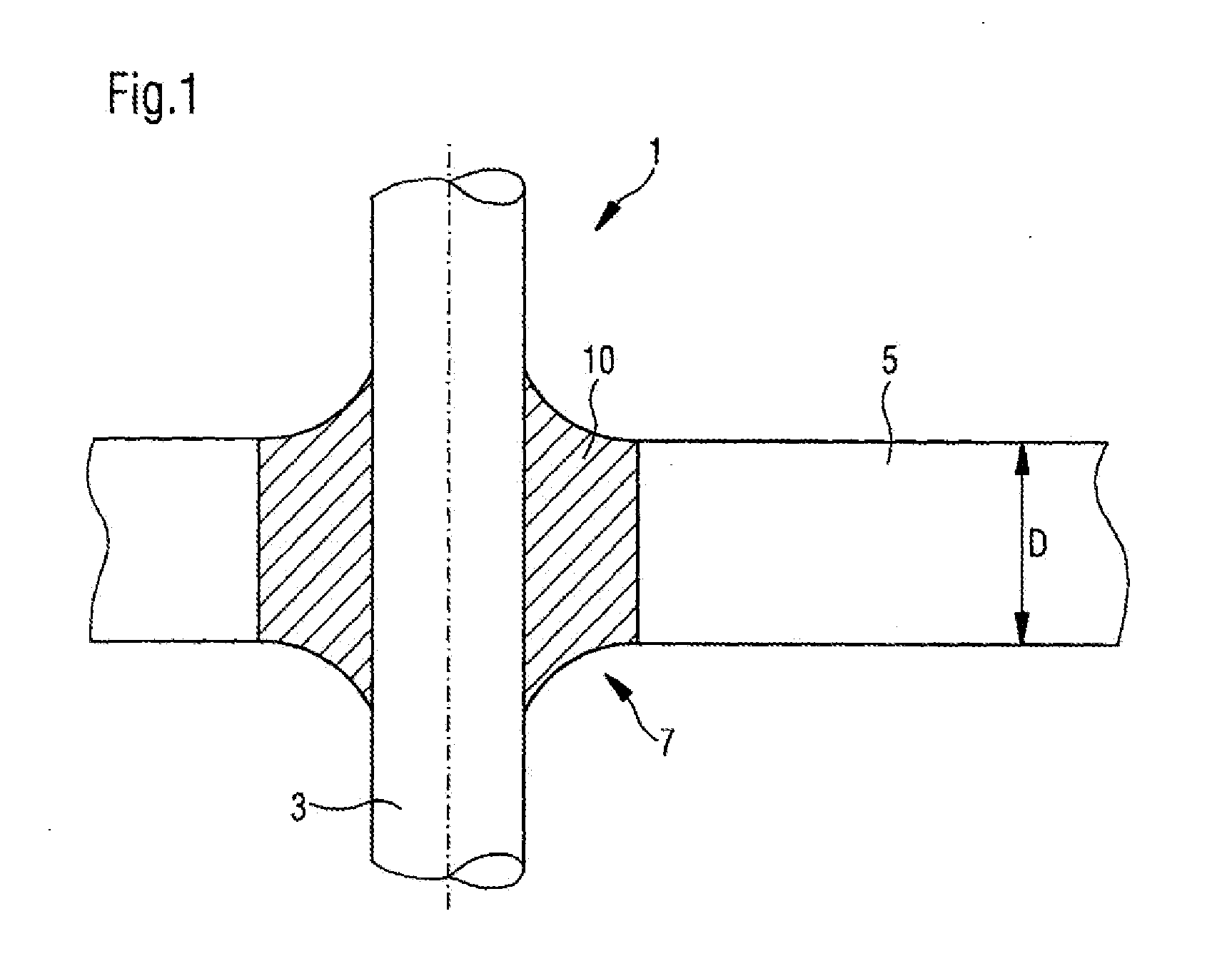
[0063]Referring now to the drawing, and more particularly to FIG. 1, there is shown a feed-through 1 according to the present invention. Feed-through 1 includes a metal pin 3 as a conductor, in particular as a pin shaped conductor which consists for example of a material, such as aluminum or copper. It further includes a base body 5 in the embodiment of a metal part consisting according to the present invention of a metal which has a low melting point, that is a light metal such as aluminum. Metal pin 3 is guided through an opening 7 which leads through metal part 5. Even though only the insertion of a single metal pin through the opening is illustrated, several metal pins could be inserted through the opening, without deviating from the present invention.

[0064]The outer contour of opening 7 can be round, but also oval. Opening 7 penetrates through the entire thickness D of base body 5, or respectively metal part 5. Metal pin 3 is sealed into a glass material 10 and is inserted insi...


PUM

PropertyMeasurementUnit
temperatureaaaaaaaaaa
melting temperatureaaaaaaaaaa

Abstract

A glass, for example a glass solder, includes the following components in mole percent (mol-%): P2O5 37-50 mol-%, for example 39-48 mol-%; Al2O3 0-14 mol-%, for example 2-12 mol-%; B2O3 2-10 mol-%, for example 4-8 mol-%; Na2O 0-30 mol-%, for example 0-20 mol-%; M2O 0-20 mol-%, for example 12-20 mol-%, wherein M is, for example, K, Cs or Rb; Li2O 0-42 mol-%, for example 0-40 mol-% or 17-40 mol-%; BaO 0-20 mol-%, for example 0-20 mol-% or 5-20 mol-%; and Bi2O3 0-10 mol-%, for example 1-5 mol-% or 2-5 mol-%.

Description

CROSS REFERENCE TO RELATED APPLICATIONS [0001]This is a continuation of PCT application No. PCT / EP2012 / 000703, entitled “GLASS, IN PARTICULAR GLASS SOLDER OR FUSIBLE GLASS”, filed Feb. 17, 2012 which is incorporated herein by reference.BACKGROUND OF THE INVENTION[0002]1. Field of the Invention[0003]The present invention relates to a glass and by association to a glass composition, in particular a solder glass as well as to a feed-through for a storage device, such as a lithium-ion battery, for example a lithium-ion accumulator.[0004]2. Description of the Related Art[0005]Solder glasses or fusible glasses are glasses which are used to bond metals having a high heat expansion and low melting temperature, for example by means of soldering with a solder glass or sealing by means of a fusible glass.[0006]Glasses which find use as solder glasses are known from a multitude of patent specifications. For example, U.S. Pat. No. 5,262,364 describes a high expansion solder glass comprising 10-2...

Claims


Application Information

Patent Timeline
Patent Type & Authority Applications(United States)
IPC IPC(8): C03C8/00H01M2/06H01M50/176H01M50/188H01M50/191H01M50/529H01M50/55H01M50/553H01M50/562H01M50/564H01M50/566
CPCC03C8/00H01M2/065C03C3/19C03C4/20C03C8/24H01M10/0525Y10T29/49115Y10T29/4911Y10T29/49108B23K2101/36B23K2103/10Y02E60/10H01M50/186H01M50/191C03C29/00H01M50/562H01M50/564H01M50/55H01M50/553H01M50/176H01M50/566H01M50/188H01M50/172H01M10/0569H01M2220/20H01M2300/0037C03C2204/00C03C2207/08C03C27/02H01M50/529B23K15/0093B23K26/32H01M50/543C03C17/02H01M50/183B23K1/19
Inventor GOEDEKE, DIETERBACKNAES, LINDA JOHANNA
Owner SCHOTT AG
Learn More