Oscillating impact grinding blade

Inactive Publication Date: 2013-12-12
L R OLIVER
View PDF17 Cites 13 Cited by
  • Summary
  • Abstract
  • Description
  • Claims
  • Application Information

AI Technical Summary

Benefits of technology

[0014]One advantage of the present invention may be that it provides an improved oscillating impact grinding blade for use with an oscillating tool.
[0015]Still another advantage of the present invention may be that it provides an improved oscillating impact grinding blade for use in removing masonry joint fillers, such as grout and mortar.
[0016]Still another advantage of the present invention may be that it provide an oscillating impact grinding blade that has a wave form pattern arranged or formed onto the outer peripheral cutting edge of the blade.
[0017]Yet another advantage of the present

Problems solved by technology

There have been some problems in the prior art with the removal of masonry filler or grout while using an oscillating blade.
Therefore, the overall design of the oscillating multi-tool makes it very versatile and offers many benefits, however, there have been problems with the material removal rate of oscillating multi tools.
Hence, a multi-tool abrasive blade with its relatively low peripheral speed only has the individual grits on the abrasive blade hammering away at the masonry or grout filler at a relatively low contact speed and thus are not able to clear away the material very quickly.
Furthermore, the prior art also has a problem with the relatively

Method used


Image

  • Oscillating impact grinding blade
  • Oscillating impact grinding blade
  • Oscillating impact grinding blade

Examples


Embodiment Construction

)

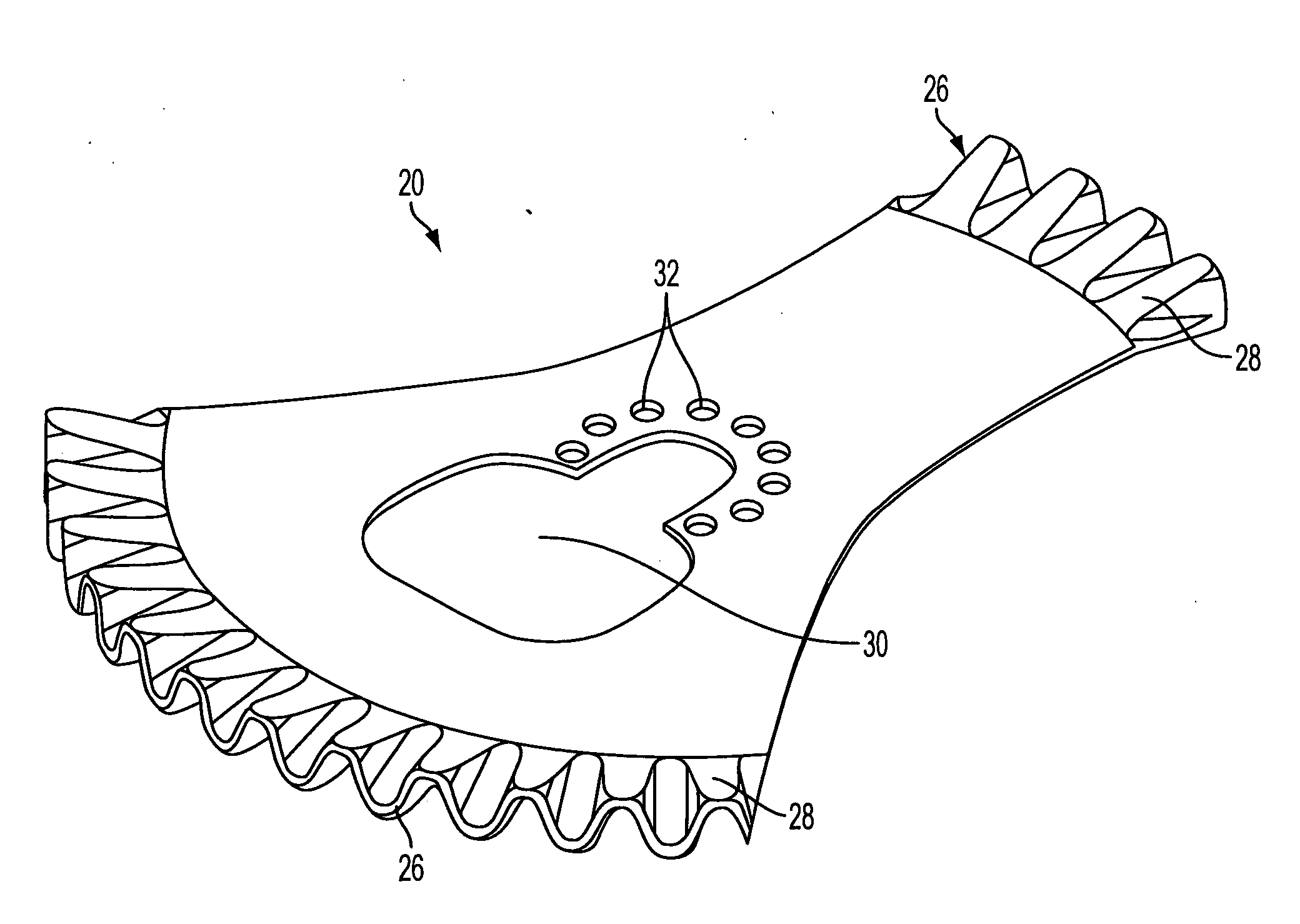
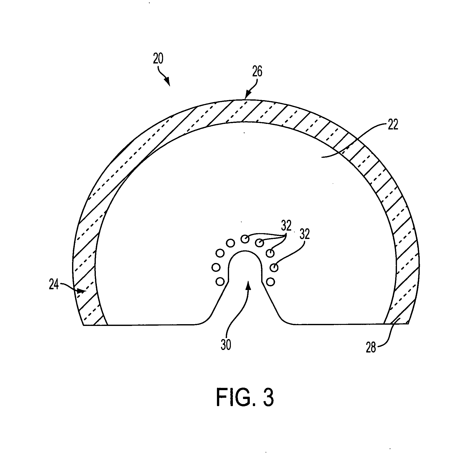
[0031]Referring to the drawings, the present invention of an oscillating blade 20 for use with an oscillating tool is shown. It should be noted that the oscillating blade 20 may use an abrasive grit structure that is selectively attachable to a tool or blade surface of a tool which uses the oscillating blade 20 or the like. Applicant has developed various methods and apparatuses for connecting and molding grits and / or teeth like structures to tools, blades or other surfaces, and the present invention may be used with any of the Applicant's previous inventions and therefore, the Applicant hereby incorporates by reference prior U.S. Pat. Nos. Re 35,812, 4,916,869 and 6,821,196.

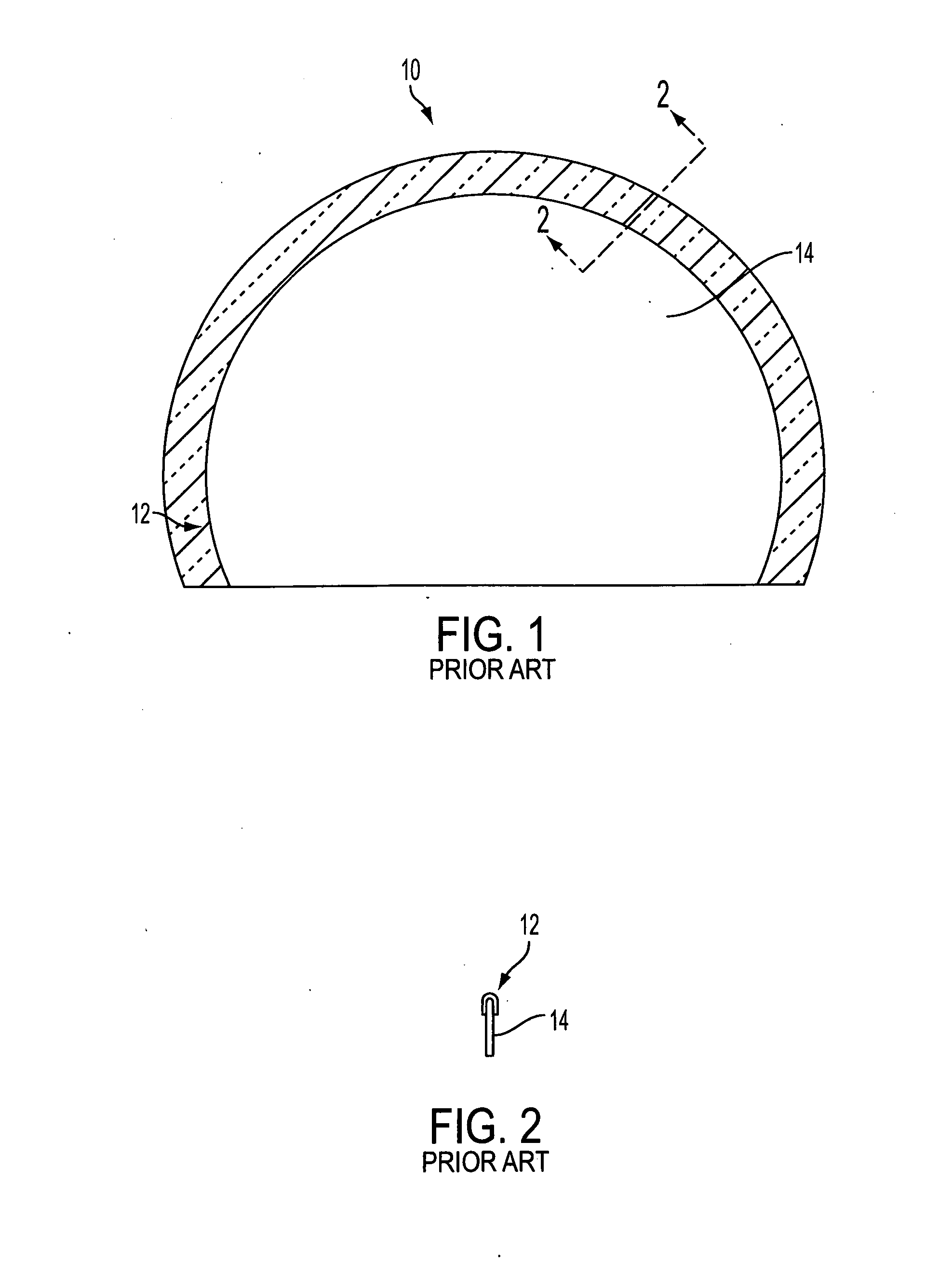
[0032]FIGS. 1 and 2 show a prior art oscillating blade 10 that may be used for removing grout. This prior art blade 10 generally has a thin circular body 14 that is typically made of a sheet steel and armed with abrasive grains 12 of tungsten carbide or diamond grit on an edge thereof. These typical prior art g...


PUM

PropertyMeasurementUnit
Thicknessaaaaaaaaaa
Lengthaaaaaaaaaa
Shapeaaaaaaaaaa

Abstract

An oscillating blade for use with an oscillating tool comprises a base having a predetermined shape and thickness. The oscillating blade also comprises a cutting edge located on a predetermined portion of the circumferential edge of the base. An abrasive coating layer encapsulates the cutting edge and a predetermined wave form is incorporated into the cutting edge. This may allow for the oscillating blade to more efficiently and quickly remove mortar or grout from in between joints of tile, brick, or the like.

Description

BACKGROUND OF THE INVENTION[0001]1. Field of the Invention[0002]The present invention generally relates to an oscillating impact grinding blade, and more particularly, relates to an oscillating blade for use in an oscillating power tool for removal of masonry or joint masonry fillers.[0003]2. Description of Related Art[0004]Abrasive grit tool structures have been known for numerous years. Generally, the abrasive grit tool structures include devices such as grinding wheels, hand tools, and the like which generally have an outer grit particle surface which is used to remove portions of a work piece for shaping and / or finishing a work piece. In many prior art structures, abrasive grits have been attached to power tool accessory or hand tool surfaces by placing a single layer of grit particles on a tool form and then binding the grits to the tool by using a brazing metal or by an electro plating coating which grips the grit particles. Generally, in the prior art, the removal of grout an...

Claims


Application Information

Patent Timeline
IPC IPC(8): B28D1/12B24D18/00
CPCB23D61/006B24D5/12B28D1/12B24D18/00
Inventor NEAL, JR., WYATT W.GIRARDIN, RALPHPEDERSEN, BRYAN
Owner L R OLIVER
Why Eureka
Try Eureka