Chain guide and chain tensioner device

a chain tensioner and guide base technology, applied in the direction of belts/chains/gears, mechanical equipment, mechanical components, etc., can solve the problems of increased noise and mechanical loss, and achieve the effects of reducing the thickness of the pillar member, improving assembly work efficiency, and increasing the mechanical strength of the guide bas

Inactive Publication Date: 2013-12-12
NTN CORP
View PDF45 Cites 15 Cited by
  • Summary
  • Abstract
  • Description
  • Claims
  • Application Information

AI Technical Summary

Benefits of technology

[0056]With the chain guide according to the present invention, the roller can be supported between the mutually facing wall surfaces of the side plate members constituting the guide base only by dropping the support shaft of the roller into the support recess provided in each of the mutually facing wall surfaces of the side plate members so as to be fitted therein, and hence the assembly work efficiency is improved.
[0057]Further, the guide base includes the mutually facing side plate members respectively provided along opposite sides of the chain, and the pillar members connecting the side plate members to each other, and is configured such that the direction of the pillar members connecting the side plate members to each other is formed to be aligned in parallel with the insertion direction of the support shaft into the support recess. Therefore, the pillar members provided between the support recesses can be formed thickly, and hence the mechanical strength of the guide base can be increased.
[0058]That is, when the direction of the pillar members is not in parallel with the insertion direction of the support shaft into the support recess, the pillar member cannot be arranged between the support recesses unless the thickness of the pillar member is reduced.
[0059]Further, when the direction of the pillar members connecting the side plate members to each other is formed to be aligned in parallel with the insertion direction of the support shaft into the support recess, the drawing directions of the mold for forming the pillar members and the support recesses can be set to the same direction, and hence the mold can be manufactured at low cost.
[0060]Further, when the height of the side plate member is set lower than the position of the connection pin of the chain which runs while being in contact with the rollers, the connection pin of the chain is not brought into contact with the side plate member, so that the wear of the side plate member can be prevented.
[0061]Further, the portion of the roller which is brought into contact with the chain is the steel outer ring of the roller bearing. Therefore, the portion has high mechanical strength and low sliding resistance, and is difficult to wear even when being brought into contact with the chain running at high speed. Further, the chain guide is configured such that the steel outer ring of the roller bearing is brought into direct contact with the chain. Thereby, the number of components can be reduced, and the cost and weight of the chain guide can be reduced.

Problems solved by technology

The chain guide is configured to guide the chain while being in contact with the chain, and hence sliding resistance is generated due to friction between the chain guide and the chain, causing a problem of an increased noise and mechanical loss.

Method used


Image

  • Chain guide and chain tensioner device
  • Chain guide and chain tensioner device
  • Chain guide and chain tensioner device

Examples


Embodiment Construction

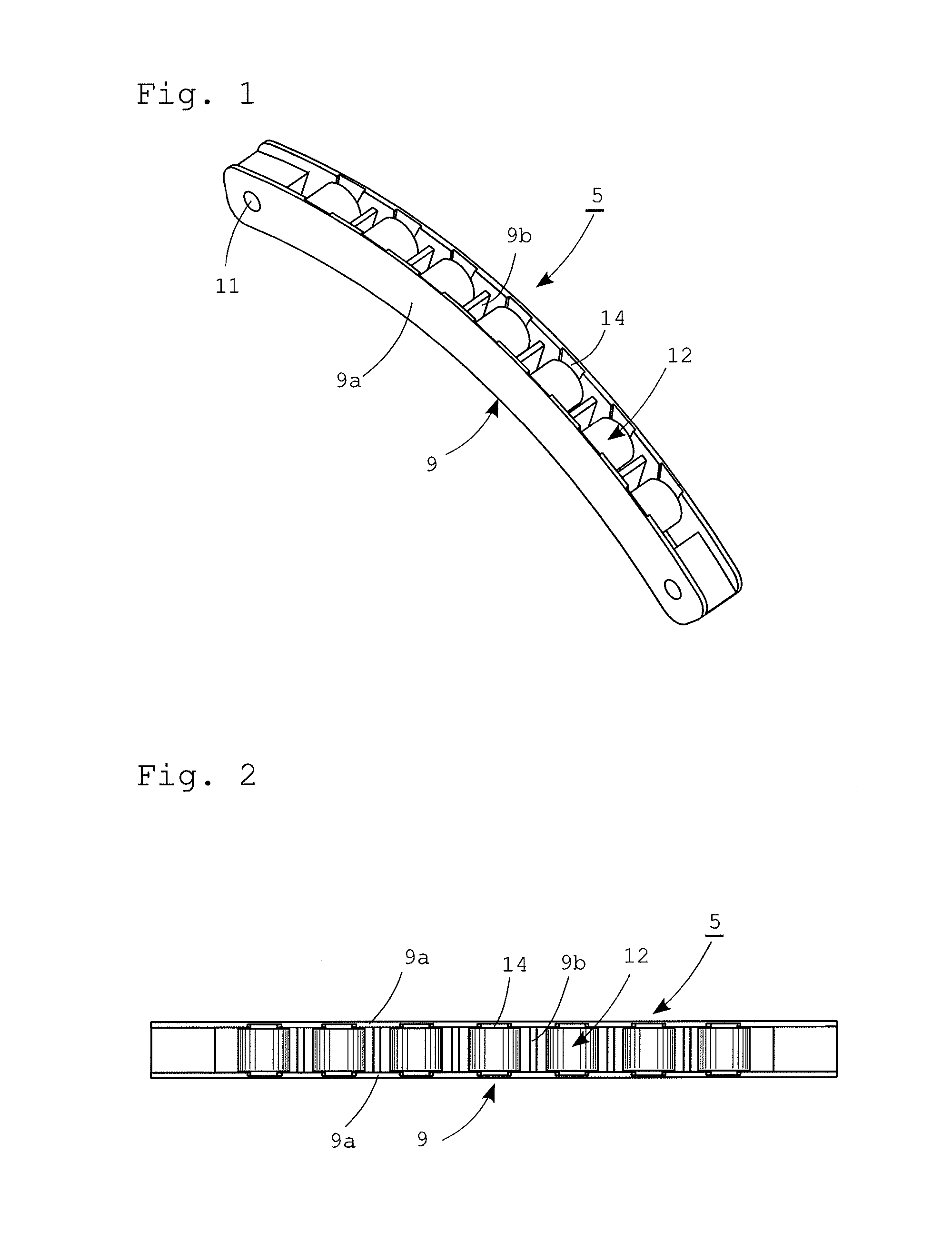
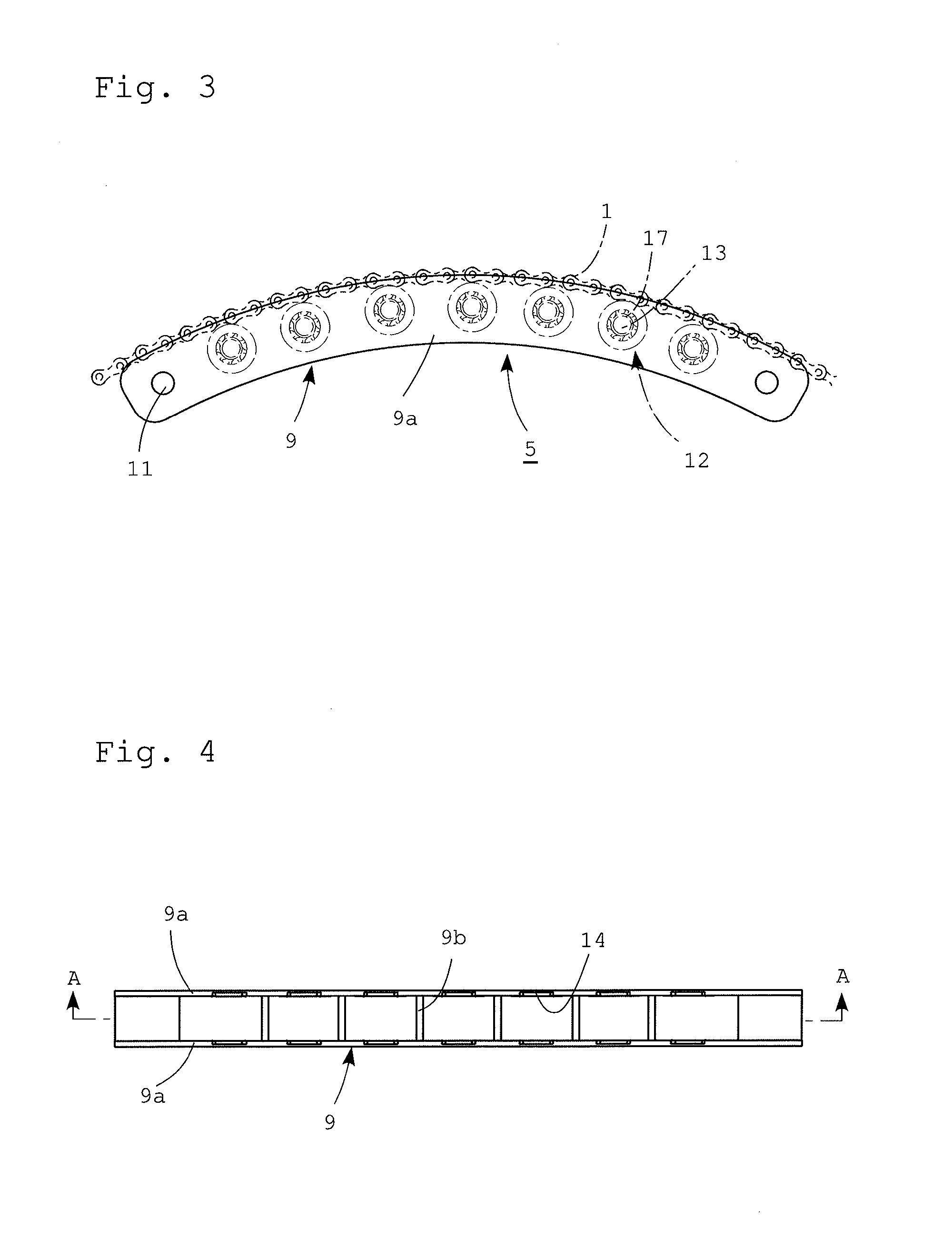
[0082]Embodiments according to the present invention will be described in detail with reference to the accompanying drawings. Note that components, which are the same or equivalent to each other, are denoted by the same reference numeral or character in the drawings, and the description thereof is not repeated to avoid duplication of description.

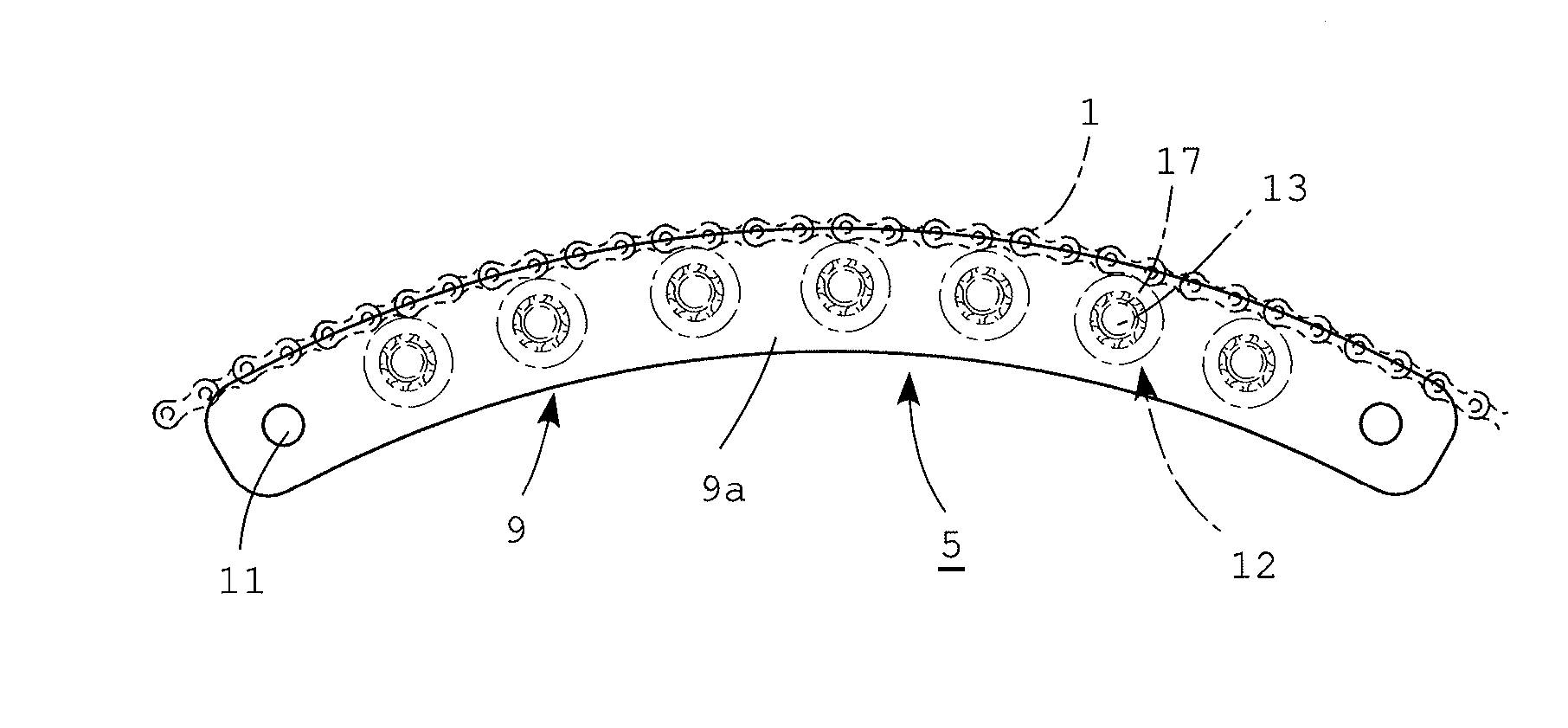
[0083]A chain guide according to an embodiment of the present invention is used, for example, for giving tension to a timing chain of an engine valve drive system.

[0084]As shown in FIG. 19, a timing chain 1 is endlessly wound around a crank sprocket 2 attached to a crankshaft, and a first cam sprocket 3 and a second cam sprocket 4 attached to a first cam shaft and to a second cam shaft of a valve train, respectively.

[0085]A first chain guide 5a and a second chain guide 5b are respectively arranged on the timing chain 1 between the crank sprocket 2 and the first cam sprocket 3, and on the timing chain 1 between the crank sprocket 2 and the se...


PUM


Abstract

A chain guide and a chain tensioner device using the chain guide. A roller, brought into contact with a chain, comprises a support shaft supported by an opposing guide base provided along the running direction of the chain, and roller bearings each having a steel outer ring on the outer peripheral surface of the support shaft so as to be brought into contact with the chain. The roller is also configured to be assembled by inserting opposite ends of the support shaft into support recesses on facing wall surfaces of the guide base. The roller, has a vibration damping material between the support shaft and the support recess of each of the plate members.

Description

TECHNICAL FIELD[0001]The present invention relates to a chain guide which presses an endlessly connected chain and thereby gives tension to the chain so as to prevent the slacking of the chain, and also relates to a chain tensioner device.BACKGROUND ART[0002]A chain tensioner device is provided with chain guides which are brought into contact with middle portions of a chain endlessly provided around drive and driven sprockets and running at high speed, and is configured to press at least one of the chain guides against the chain in the direction substantially perpendicular to the running direction of the chain to thereby apply tension to the chain so as to prevent the chain from slacking. The chain tensioner device is used for a timing chain, or the like, of a valve driving device of an engine.[0003]The chain guide is configured to guide the chain while being in contact with the chain, and hence sliding resistance is generated due to friction between the chain guide and the chain, c...

Claims


Application Information

Patent Timeline
Patent Type & Authority Applications(United States)
IPC IPC(8): F16H7/12
CPCF16H7/12F16H7/18F16H2007/0872F16H2007/0865F16H2007/0891
Inventor KATO, AKIOYAMASHITA, TAKAHIROABE, KATSUFUMI
Owner NTN CORP
Why Eureka
Try Eureka