Physiological sensor delivery device and method

a sensor and sensor technology, applied in the field of medical device technology, can solve the problems of inaccurate pressure drop reading, error introduction, and inability to seal well around the catheter, and achieve the effect of facilitating sensor positioning

Active Publication Date: 2013-12-12
ACIST MEDICAL SYST
View PDF0 Cites 36 Cited by
  • Summary
  • Abstract
  • Description
  • Claims
  • Application Information

AI Technical Summary

Benefits of technology

[0012]An intravascular sensor delivery device according to some embodiments of the invention comprises a distal sleeve with a guidewire lumen for sliding over a medical guidewire, a sensor coupled to the distal sleeve, the sensor adapted to measure a physiological parameter of a patient and generate a signal representative of the physiological parameter. A proximal portion is coupled to the distal sleeve. The proximal portion comprises a communication channel for communicating the signal from the sensor to a location outside of the patient (such as a display monitor, or another medical device, etc.). The proximal portion of the sensor delivery device is adapted to facilitate positioning of the sensor within a vascular structure of the patient.

Problems solved by technology

A disadvantage of using this method is that some error may be introduced due to the cross sectional size of the catheter.
However, because of the catheter size, the heart valve may not seal well around the catheter.
Leakage might also result from the presence of the catheter and may contribute to an inaccurate pressure drop reading.
Advancing and maneuvering a pressure sensing guidewire though stenotic lesions and the vasculature, for example, can be a difficult and / or time consuming task.
A pressure sensing guidewire may have torque and flexing characteristics that are either unknown to the physician, or that are unsuitable for a particular task, because such a guidewire is specifically constructed to have a pressure sensor incorporated as part of the guidewire itself.
As a result, a physician may find it difficult to maneuver a pressure sensing guidewire into an anatomical location of interest, as compared to a “standard” (e.g., non-pressure sensing) medical guidewire.
Having grown accustomed to the handling characteristics of a particular non-pressure sensing guidewire, a physician may be reluctant to employ a pressure sensing guidewire, which may increase the time and difficulty of positioning and repositioning the pressure sensing guidewire across a stenotic lesion, for example.

Method used


Image

  • Physiological sensor delivery device and method
  • Physiological sensor delivery device and method
  • Physiological sensor delivery device and method

Examples


Embodiment Construction

[0035]The following detailed description should be read with reference to the accompanying drawings, in which like numerals denote like elements. The drawings, which are not necessarily to scale, depict selected embodiments of the invention—other possible embodiments may become readily apparent to those of ordinary skill in the art with the benefit of these teachings. Thus, the embodiments shown in the accompanying drawings and described below are provided for illustrative purposes, and are not intended to limit the scope of the invention as defined in the claims appended hereto.

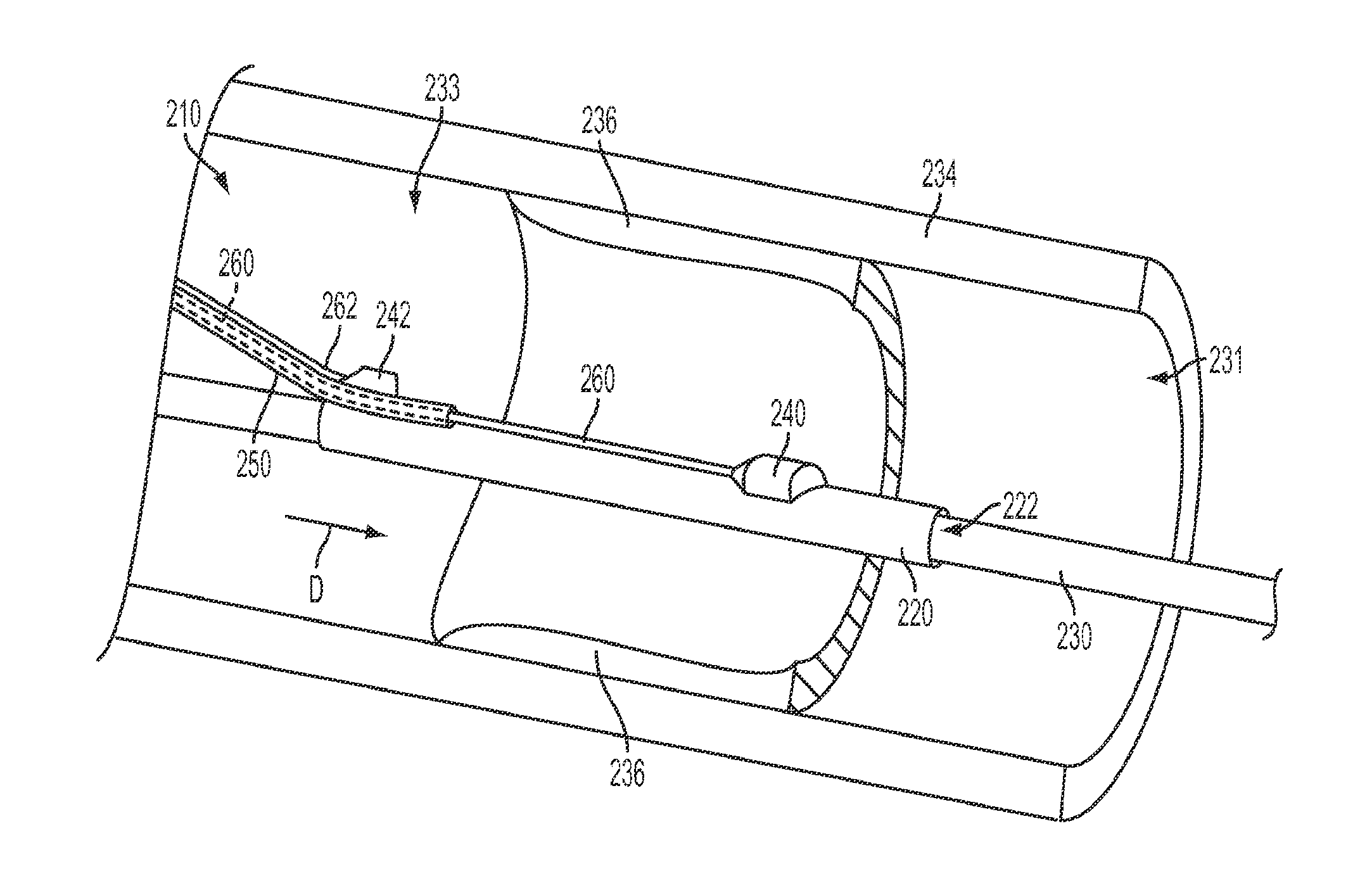
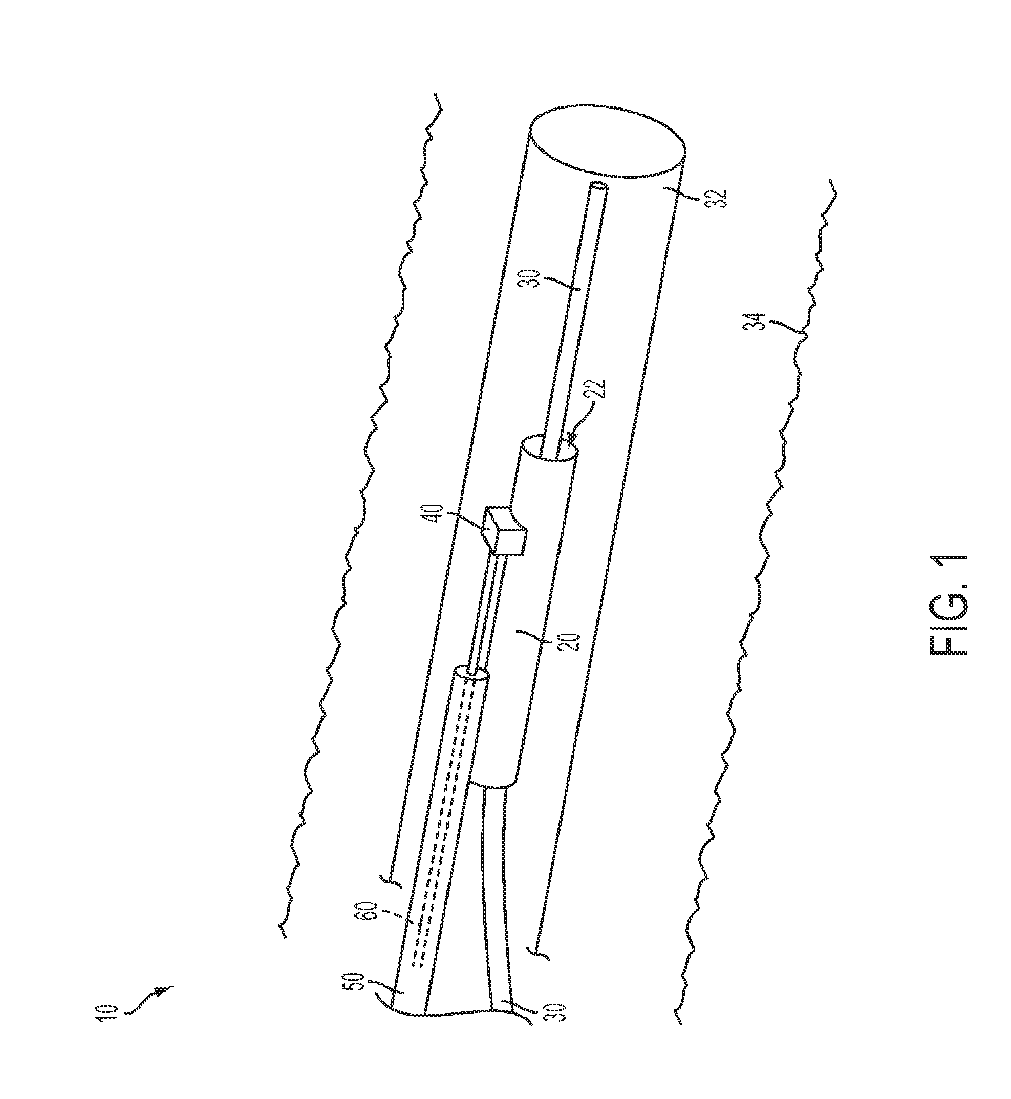
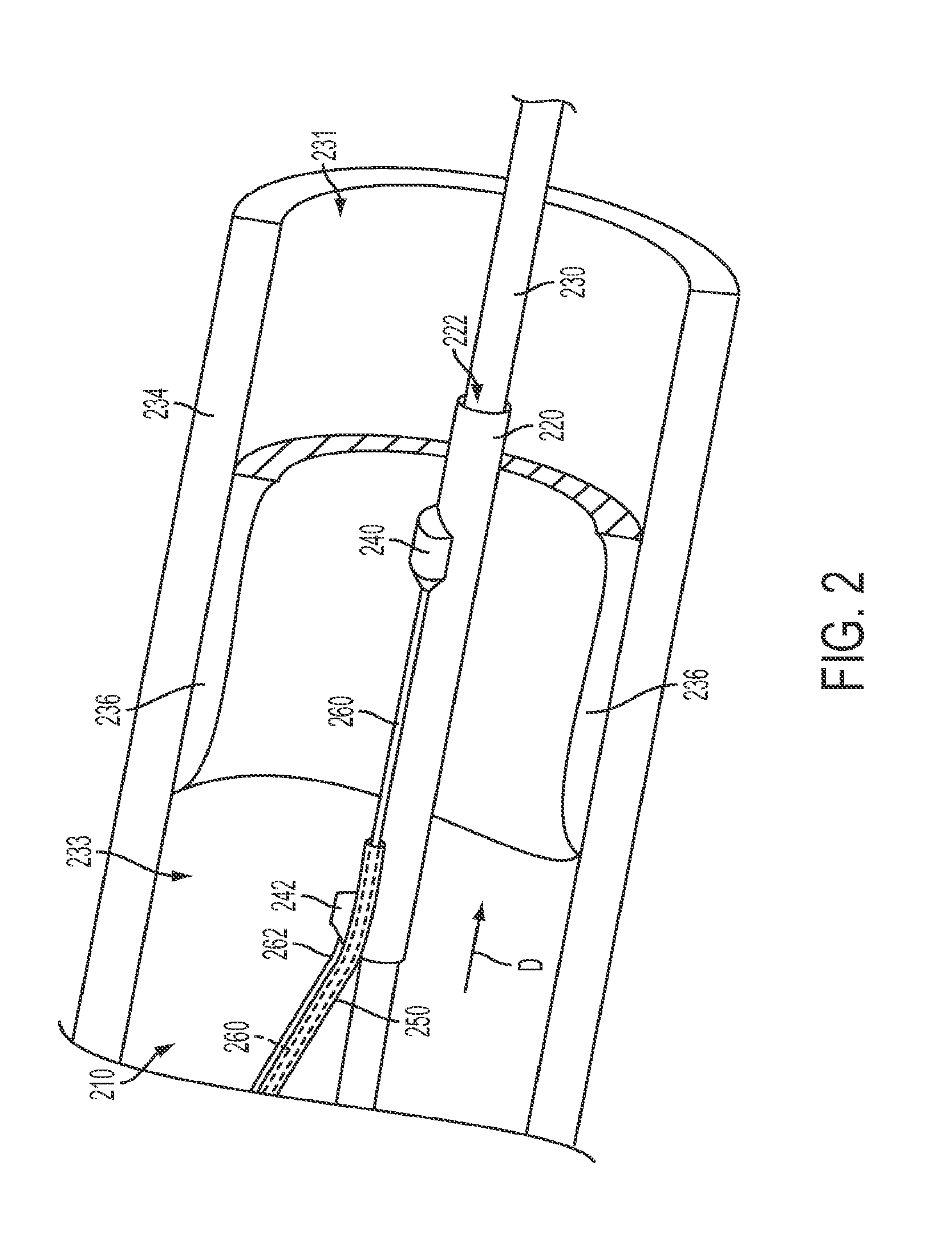
[0036]An example of a sensor delivery device according to certain embodiments of the invention is shown in FIG. 1. The sensor delivery device 10 of FIG. 1 includes a distal sleeve 20 having a guidewire lumen 22 for slidably receiving a medical guidewire 30. A sensor 40 is coupled to the distal sleeve 20, sensor 40 being capable of sensing and / or measuring a physiological parameter of a patient and generating...


PUM


Abstract

An intravascular sensor delivery device for measuring a physiological parameter of a patient, such as blood pressure, within a vascular structure or passage. In some embodiments, the device can be used to measure the pressure gradient across a stenotic lesion or heart valve, such as a fractional flow reserve (FFR) across a stenotic lesion. The sensor delivery device has a distal sleeve configured to pass or slide over a standard medical guidewire. The sensor delivery device can be sized to pass over different sizes of guidewires to enable usage in coronary and peripheral arteries, for example. The sensing mechanism (sensor) can be a fiber optic pressure sensor, such as a MEMS-based FabryPerot fiber optic pressure sensor, for example, or could employ some other technology, e.g., MEMS capacitive or piezoresistive sensor.

Description

CROSS-REFERENCE TO RELATED APPLICATIONS[0001]This application is a divisional of U.S. patent application Ser. No. 13 / 350,158, filed Jan. 13, 2012, which is a continuation of U.S. patent application Ser. No. 12 / 557,685, filed Sep. 11, 2009, now U.S. Pat. No. 8,298,156 issued Oct. 30, 2012, which claims priority to U.S. Provisional Patent Application No. 61 / 096,216, filed Sep. 11, 2008. The entire contents of these applications are incorporated herein by reference.TECHNICAL FIELD[0002]This application relates generally to the field of medical device technology and, more particularly, to devices and methods for positioning and utilizing physiological sensors in anatomical (e.g., vascular) structures of patients, such as in blood vessels or across heart valves.BACKGROUND[0003]Certain physiological measurements may be made by positioning a sensor within a patient. Such physiological measurements may include, for example, measurements of blood parameters, such as blood pressure, oxygen sa...

Claims


Application Information

Patent Timeline
Patent Type & Authority Applications(United States)
IPC IPC(8): A61B5/0215
CPCA61B5/01A61B5/14552A61B5/0215A61B5/02154A61B5/02158A61B5/145A61M25/0029A61M25/0067A61M25/007A61M2025/0002A61M2025/0034A61M2025/0037A61M2025/0183A61B6/507A61B5/02007A61B5/02014A61B5/0225A61M1/36A61B5/0261A61B5/02055A61B5/0002A61B5/6851A61B5/742A61M5/007A61B5/0022A61B5/02028A61B5/0017A61B5/6853A61B5/6862A61B2562/12A61M2025/091A61M25/09
Inventor MANSTROM, DALE R.RAATIKKA, AMY R.WILSON, ROBERT F.MILLER, EDWARD R.PAK, JUNG KWON
Owner ACIST MEDICAL SYST
Why Eureka
Try Eureka