Coupling arrangement

a coupling arrangement and mechanical technology, applied in the direction of couplings, rod connections, manufacturing tools, etc., can solve the problems of low load bearing capacity of aluminium scaffolds, severe weakening of material in heat affected zones, and high weight of steel scaffolds, so as to simplify the assembly of mechanical coupling arrangements and ensure the effect of rotational symmetry cross-sectional surfa

Active Publication Date: 2013-12-19
PLUSEIGHT TECH AB
View PDF16 Cites 3 Cited by
  • Summary
  • Abstract
  • Description
  • Claims
  • Application Information

AI Technical Summary

Benefits of technology

[0019]The pole and/or said mounting collar may have substantially rotational symmetric cross-sectional surface, because this arrangement allows the mounting collar to be mounted onto the pole in several different angular positions, thus simplifying assembly of the mechanical coupling arrangement.
[0020]The attachment means may comprise at least one flange provided on said mounting collar as attachment means for external members. Alternatively, at least one hole may be provided within said mounting collar, for example for receiving a connector. According to yet another alternative, the internal surface of the mounting collar may jointly with the external surface of the pole in said second relative angular position define at least one cavity for receiving a hook-shaped connector. This has the advantage of not requiring any formation of holes after extrusion of the parts for attachment means.
[0021]Fastening means may be provided for securing said mounting collar to said pole in

Problems solved by technology

The disadvantage with this design is high weight when scaffold is made of steel, and low load bearing capacity when scaffold is made of aluminium.
A coupling arrangement for securing a mounting collar to a pole of an aluminium scaffold based on welding suffer from severely weakening of the material in the heat affected zone, both in short term as well as long term due to fatigue.
Hence, the allowed stresses in the heat affected zone are very limited, resulting in a relatively low load bearing capacity.
Both alternatives however lead to increased weight and/or cost o

Method used


Image

  • Coupling arrangement
  • Coupling arrangement
  • Coupling arrangement

Examples


first embodiment

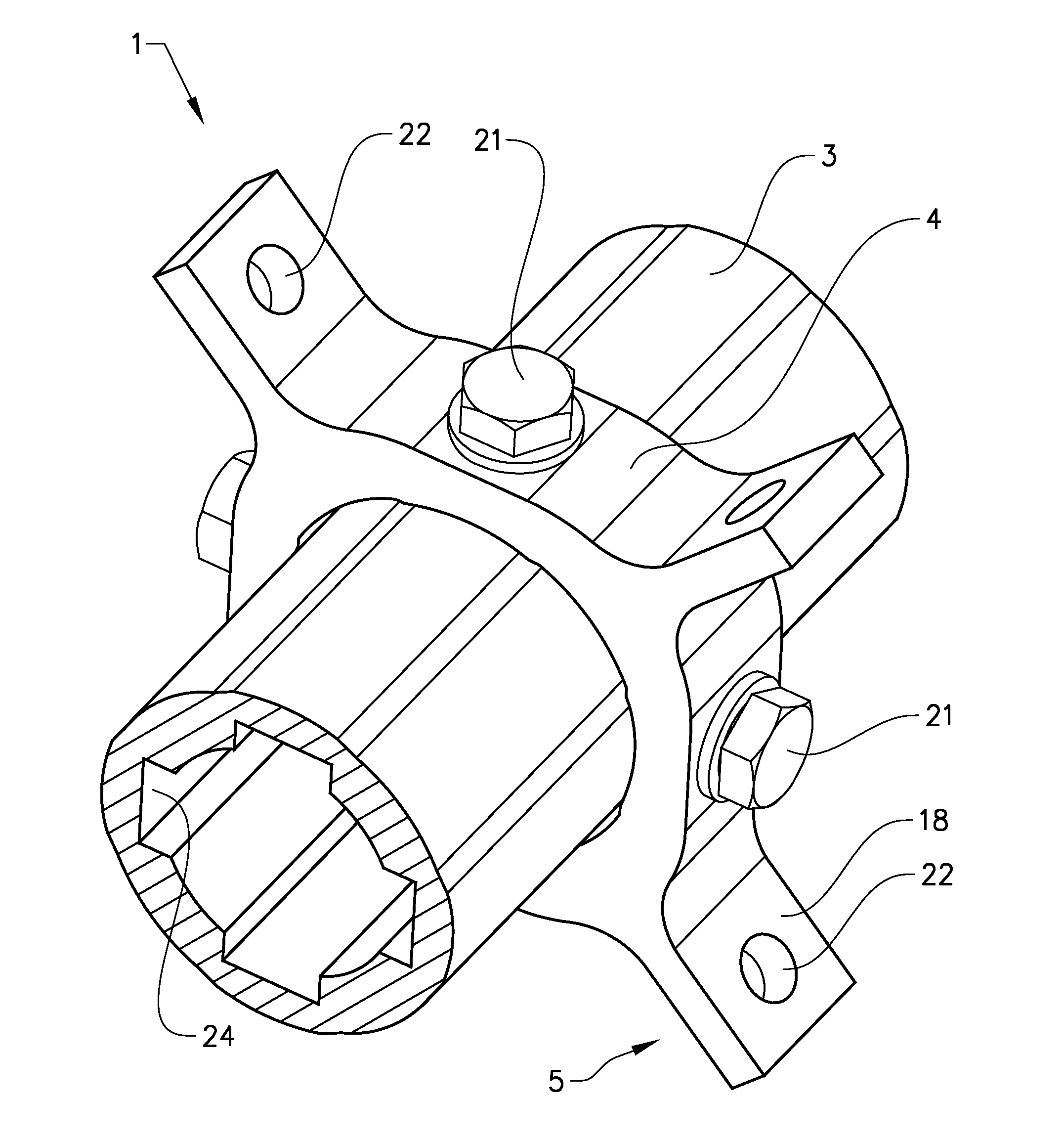
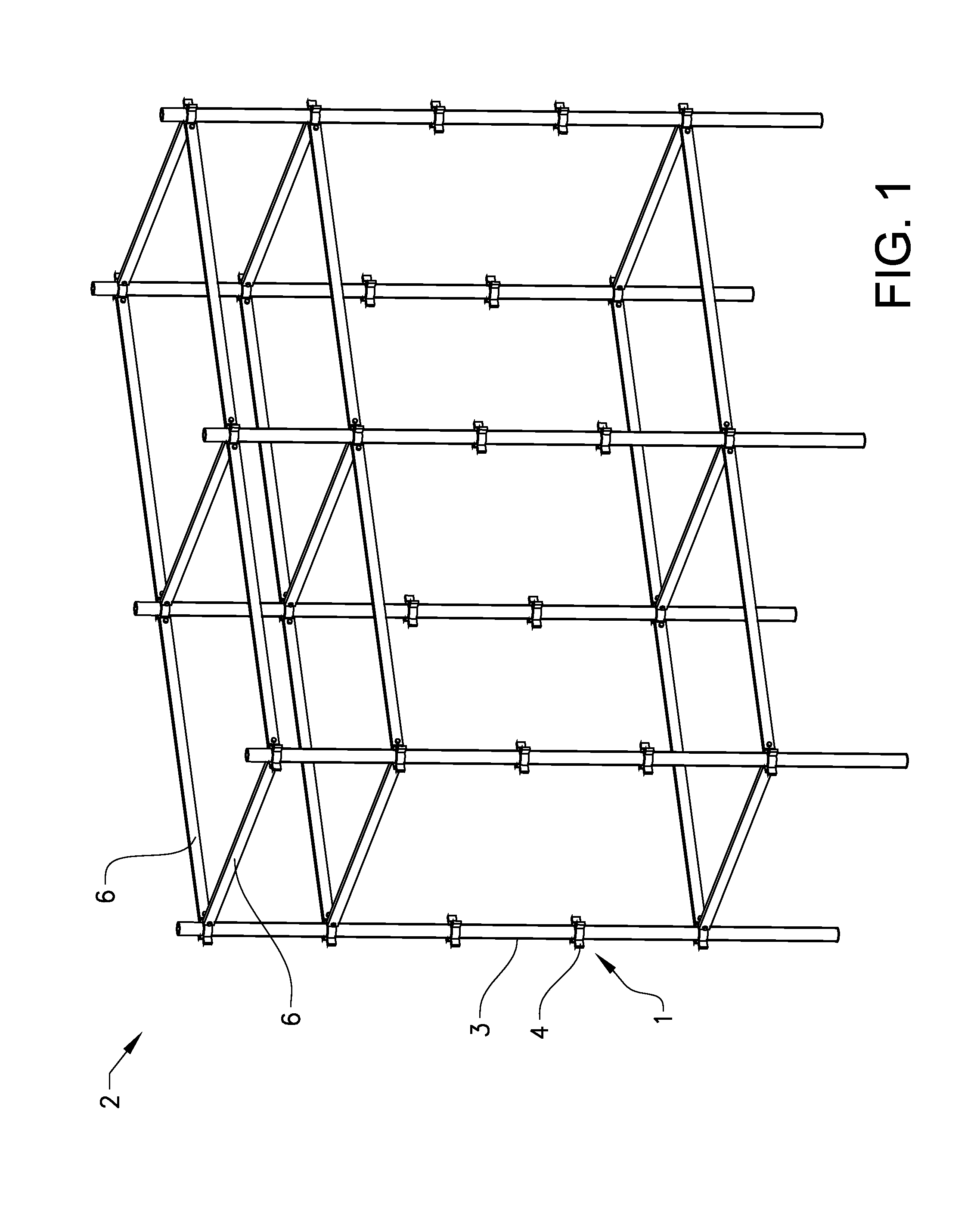
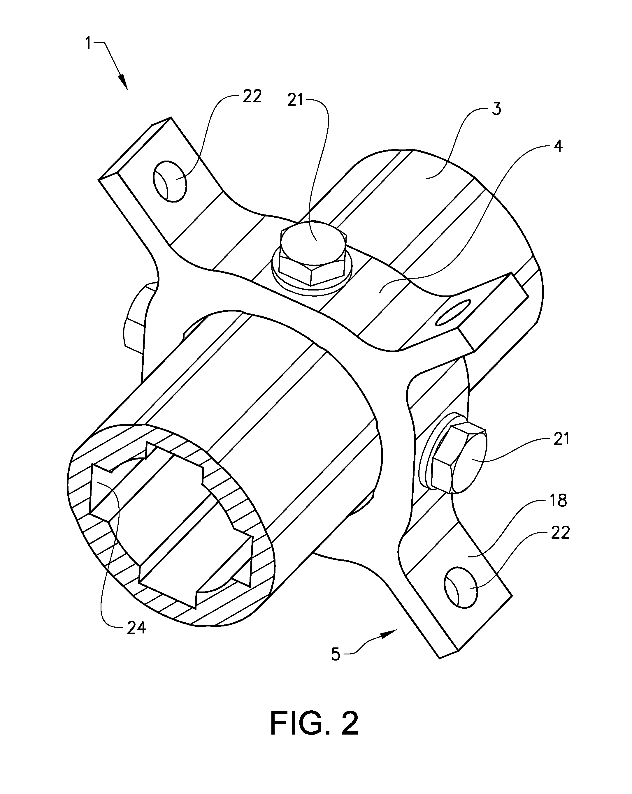
[0036]The construction of the mechanical coupling arrangement 1 will first be described with reference to FIGS. 2-6. FIG. 2 shows a three-dimensional representation of the mechanical coupling arrangement 1 of the invention. The mechanical coupling arrangement 1 of the scaffold 2 comprises a pole 3 and a mounting collar 4. The mechanical coupling arrangement 1 is formed completely without welding and does therefore not exhibit any weakening of the material in a heat-affected zone. The pole 3 is made of aluminium alloy and formed by extrusion. The pole 3 thus normally has an axially uniform cross-section except for holes formed therein for fasteners, and the exterior surface 8 at regions where the mounting collars 4 are attached is generally smooth, without threads.

[0037]The mounting collar 4 is also made of aluminium alloy. The mounting collar 4 is preferably manufactured by firstly extruding a rod, and subsequently cutting the rod in longitudinal segments, thus forming separate moun...

second embodiment

[0055]The mechanical coupling arrangement 1 according to the invention is provided with attachment means 5 for connecting elongated support members 6 to the assembled pole 3 including the mounting collars 4. The attachment means 5 comprises at least one flange 18 provided on the mounting collar 4, or at least one hole provided within the mounting collar 4 for receiving a connector or fastener. According to the mechanical coupling arrangement 1 as illustrated in FIG. 8, the shape of the mounting collar 4 is selected such that the internal surface 9 of the mounting collar 4 defines, in the second relative angular position, jointly with the external surface 8 of the pole 3 at least one cavity 19 for receiving a hook-shaped connector. This alternative has the advantage of providing attachment means 5 without further manufacturing steps of the mounting collar 4 after extrusion and cutting of the aluminium profile, from which the mounting collar 4 is formed. The mechanical coupling arrang...


PUM

PropertyMeasurementUnit
Fractionaaaaaaaaaa
Fractionaaaaaaaaaa
Fractionaaaaaaaaaa

Abstract

A mechanical coupling arrangement for a scaffold is provided. The mechanical coupling arrangement comprises a pole and a mounting collar having attachment means to which elongated support members can be attached. A level of radial play between said pole and said mounting collar in a first relative angular position is larger than the level of radial play between said pole and said mounting collar in a second relative angular position. The second relative angular position corresponds to a fastening position of said mounting collar, and in that said first relative angular position corresponds to an axial sliding position of said mounting collar.

Description

TECHNICAL FIELD[0001]The present invention relates to a mechanical non-welded coupling arrangement for a scaffold.BACKGROUND ART[0002]Mounting collars and poles of a scaffold are traditionally made of steel and welded together to form a strong component of a scaffold. Prior art document WO 01 / 33013 discloses a device for interconnecting scaffolding elements and standards of a scaffolding, wherein the mounting collar is fixedly attached for example by means of a welded joint to the pole. The disadvantage with this design is high weight when scaffold is made of steel, and low load bearing capacity when scaffold is made of aluminium.[0003]There is thus a need for an improved coupling arrangement between a mounting collar and a pole of a scaffold removing the above mentioned disadvantages.SUMMARY[0004]The object of the present invention is to provide an inventive mechanical coupling arrangement for a scaffold where the previously mentioned problems are partly avoided, wherein the mechan...

Claims


Application Information

Patent Timeline
IPC IPC(8): E04G7/14E04G7/18
CPCE04G7/14E04G7/18Y10T403/7075Y10T29/49826Y10T403/70E04G7/22E04G7/24E04G7/26E04G7/307
Inventor WALLTHER, HARRY
Owner PLUSEIGHT TECH AB
Why Eureka
Try Eureka