Flexible Compactor with Reinforcing Spine

a compactor and flexible technology, applied in the field of flexible compactors, can solve the problems of undesired fiber distortion, uneven thickness relatively complex geometries of the tool surface, so as to improve the quality and/or performance of the part, prevent permanent deformation and/or undesired, and high-speed production environment.

Active Publication Date: 2013-12-19
THE BOEING CO
View PDF4 Cites 21 Cited by
  • Summary
  • Abstract
  • Description
  • Claims
  • Application Information

AI Technical Summary

Benefits of technology

[0009]The disclosed embodiments provide a flexible compactor for transporting, placing and compacting composite stiffeners, such as stringers, that are contoured in more than one plane. The compactor places and compacts stringer layups in a cure tool in a manner that regulates and standardizes the distribution of ply wrinkling and / or ply gathering. The disclosed compaction device is flexible in multiple planes and conforms to contours of the stringer regardless of undulations in stringer geometry. Predictable ply wrinkling / gathering allows engineering changes to be made in the stringer design which compensate for the ply wrinkling and / gathering, thereby improving part quality and / or performance. The flexible compactor is robust, durable and particularly well-suited to high rate production environments. The compactor employs a reinforcing spine that prevents permanent deformation and / or undesired of buckling or kinking of the compactor.

Problems solved by technology

Compactors have been developed that are flexible along a single plane of curvature, consequently where the stringer is contoured in more than one plane, the tool surfaces have relatively complex geometries that require the compaction process to be performed by hand.
When laying up compound contoured composite stringers by hand, wrinkles may form in the laminate plies which gather at various points in the layup and / or undesired fiber distortion may occur.
Using hand layup techniques, the location of ply wrinkles and ply gathering is difficult to control, thus introducing variations in the finished part that may affect part performance.
Also, the human factor involved in hand layup may introduce process variations that lead to undesired inconsistencies in the finished parts.
Another problem with flexible compactors relates to their durability.
In areas of the compactor that are formed from rubber or a similar flexible material, repeated use of the compactor may result in undesired deformation or buckling of the rubber, causing kinking of the compactor.

Method used


Image

  • Flexible Compactor with Reinforcing Spine
  • Flexible Compactor with Reinforcing Spine
  • Flexible Compactor with Reinforcing Spine

Examples


Embodiment Construction

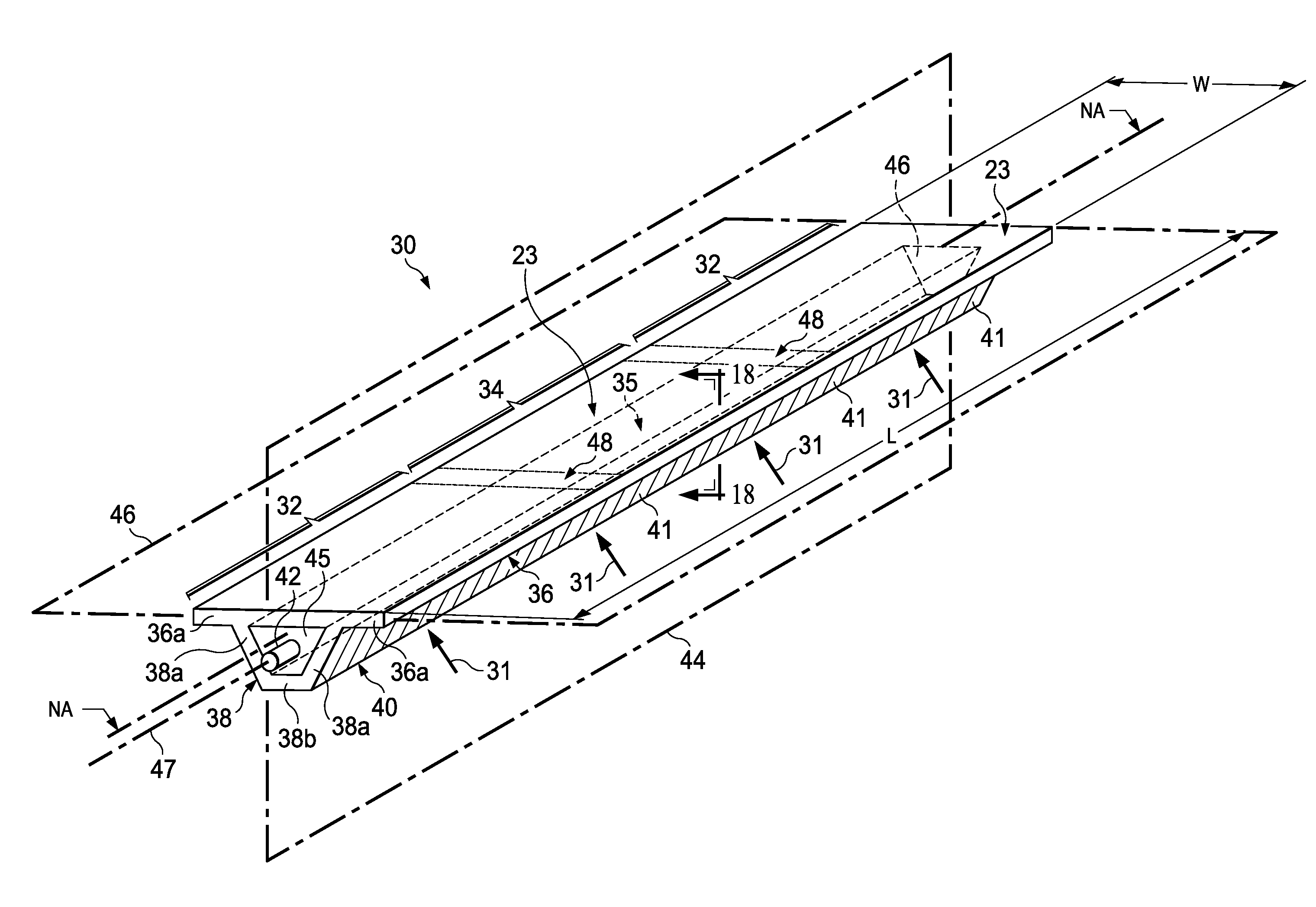
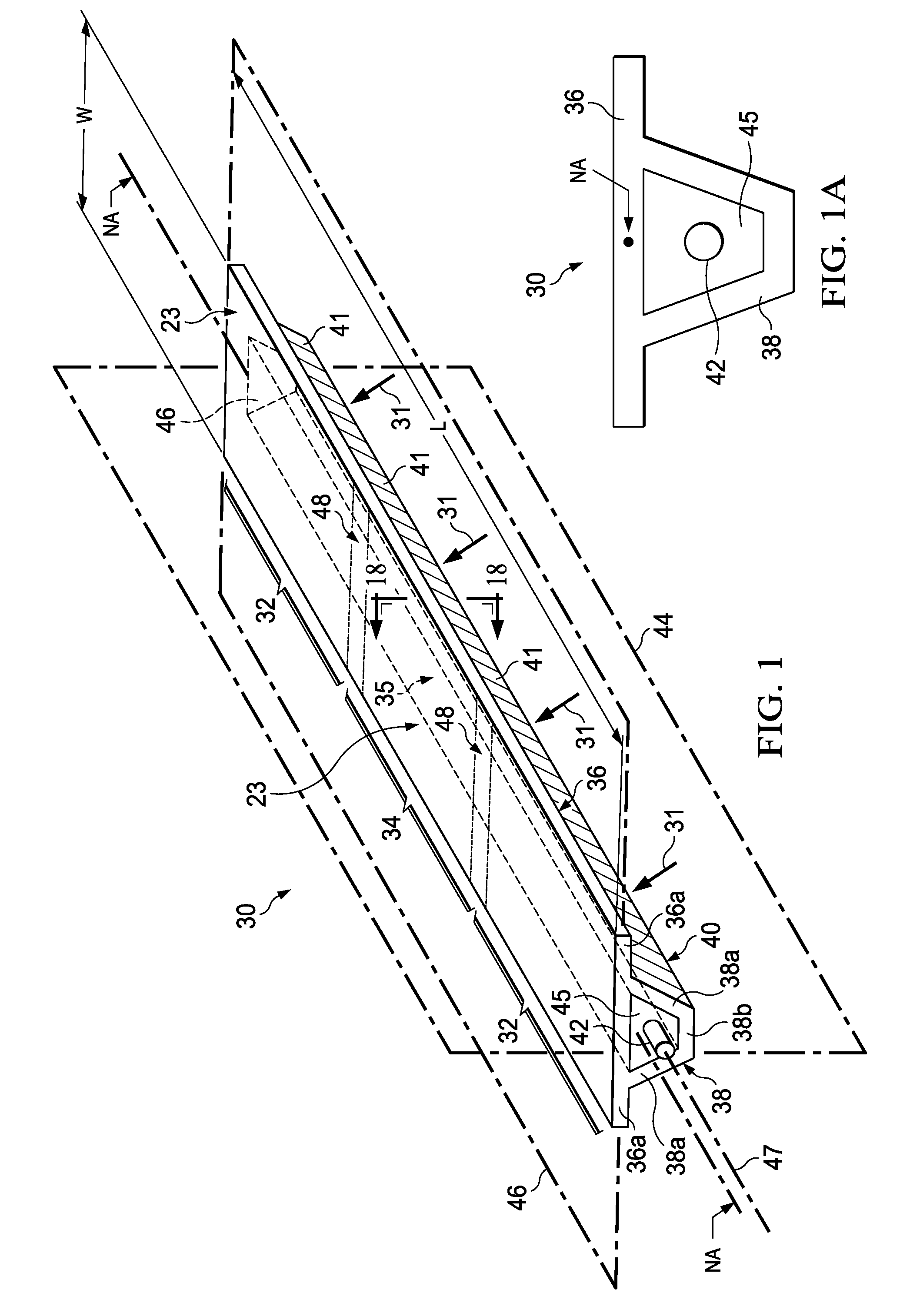
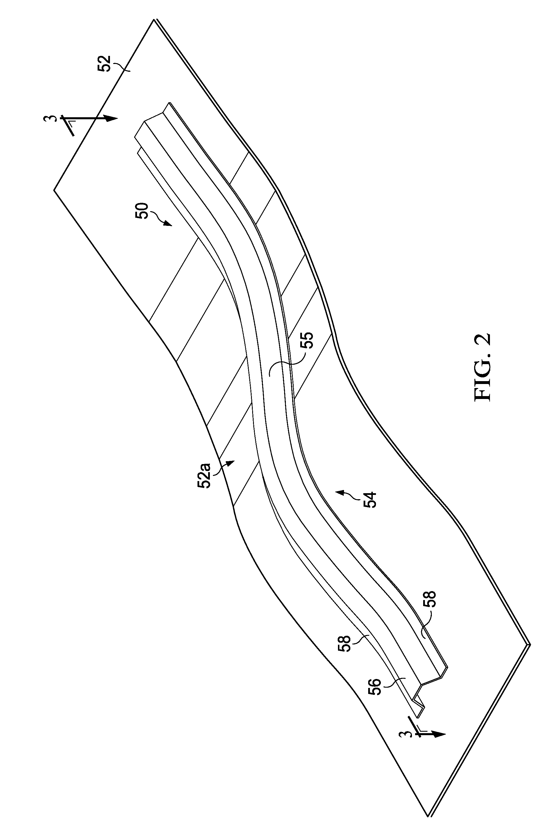
[0039]Referring first to FIGS. 1-5, a flexible compactor 30 (FIG. 1) may be used to transport, place and compact a curved composite laminate stiffener, such as without limitation, the contoured hat stringer 50 shown in FIGS. 2-5. During transport and placement of the stringer 50, the stringer 50 is held on the compactor 30 by a vacuum suction force 31. The compactor 30 is generally semi-rigid, with a degree of flexibility that allows it to flex and conform to complex tool surfaces (not shown in FIG. 1) during placement and compaction of a stringer layup in a tool. The compactor 30 is flexible in orthogonal planes 44, 46. The compactor 30 is elongate and has a longitudinal axis 47, as well as a neutral axis “NA”. The neutral axis “NA” is a line within the cross section of the compactor 30 at which substantially no extension or compression of the compactor 30 occurs when the compactor 30 bends or flexes. The compactor 30 broadly comprises a first, segmented hat portion 38, and a secon...


PUM

PropertyMeasurementUnit
widthaaaaaaaaaa
flexibleaaaaaaaaaa
thicknessaaaaaaaaaa

Abstract

A device for compacting a contoured elongate composite layup includes flexible first and second fiber reinforced resin flexible sections flexible along their lengths. The first section is flexible within a first plane and the second section is flexible within the first plane as well as within a second plane. The second section includes flexible joints reinforced by a spine.

Description

CROSS REFERENCE TO RELATED APPLICATIONS[0001]This application is a continuation-in-part of prior co-pending U.S. patent application Ser. No. 13 / 205,226 filed, Aug. 8, 2011, the entire disclosure of which is incorporated by reference herein.BACKGROUND INFORMATION[0002]1. Field[0003]The present disclosure generally relates to the fabrication composite structures, and deals more particularly with a flexible compactor for transporting, placing and compacting contoured composite stiffeners.[0004]2. Background[0005]During the fabrication of contoured composite stiffeners such as stringers, a compactor may be used to compact a layup of the stringer against tool surfaces. In some cases, the tool surfaces may be contoured along one or more planes. Compactors have been developed that are flexible along a single plane of curvature, consequently where the stringer is contoured in more than one plane, the tool surfaces have relatively complex geometries that require the compaction process to be ...

Claims


Application Information

Patent Timeline
Patent Type & Authority Applications(United States)
IPC IPC(8): B32B1/04
CPCB32B1/04B29C70/342B29C70/38B29C70/44B29D99/001B29C70/549Y10T156/17B30B11/001B30B13/00B30B15/024
Inventor STEWART, SAMUEL RAY
Owner THE BOEING CO
Why Eureka
Try Eureka