Ultrasonic device for moulding micro plastic parts

a micro-plastic part and ultrasonic technology, applied in the direction of manufacturing tools, ceramic shaping apparatus, mechanical vibration separation, etc., can solve the problems of mechanical characterization loss, subsequent reduction of quality of injected parts, etc., and achieve the effect of optimizing the quality of parts and facilitating molding

Active Publication Date: 2010-10-28
ULTRASION SL
View PDF18 Cites 6 Cited by
  • Summary
  • Abstract
  • Description
  • Claims
  • Application Information

AI Technical Summary

Benefits of technology

[0025]The rate of injection of the plastic into the mold depends, among other known factors such as the viscosity of the plastic material used, the size of the runner and the inlet diameter, on the rate and pressure in the last step of closing the mold and on the effect of the vibration.
[0026]The ultrasonic device for molding of the invention acts very quickly. The plastic material is pre-compressed, melted and injected at virtually the same time it accesses the small cavities of the mold, preventing its solidification during its travel. Molding is thereby made easier and the quality of the parts is optimized since the shear exerted on a plastic material during conventional plasticization is prevented and all the problems deriving from the dwell time of the material in the plasticizer from its entrance until the material becomes a part are eliminated.

Problems solved by technology

In both cases, and especially when dealing with micro parts, due to the little injection volume to be made in each piston stroke, there is a serious problem for the polymer if the dwell time of the molten granules inside the plasticizer exceeds their residence capacity in this medium, which is the cause of the molecular degradation of the plastic and of the subsequent reduction of quality and loss in the mechanical characterization of the injected parts, which is aggravated when a larger injectable volume is available in the machines.
However, this document does not indicate particular constructive details or details relating to the manner of assembling the sonotrode, and it even raises questions as to assessing how ultrasonic plasticization can be integrated in current injection molding machines.

Method used


Image

  • Ultrasonic device for moulding micro plastic parts
  • Ultrasonic device for moulding micro plastic parts
  • Ultrasonic device for moulding micro plastic parts

Examples


Embodiment Construction

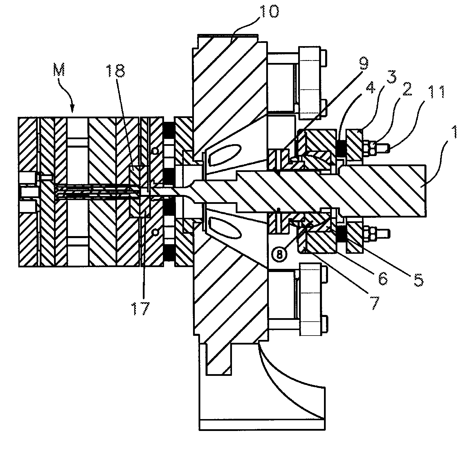
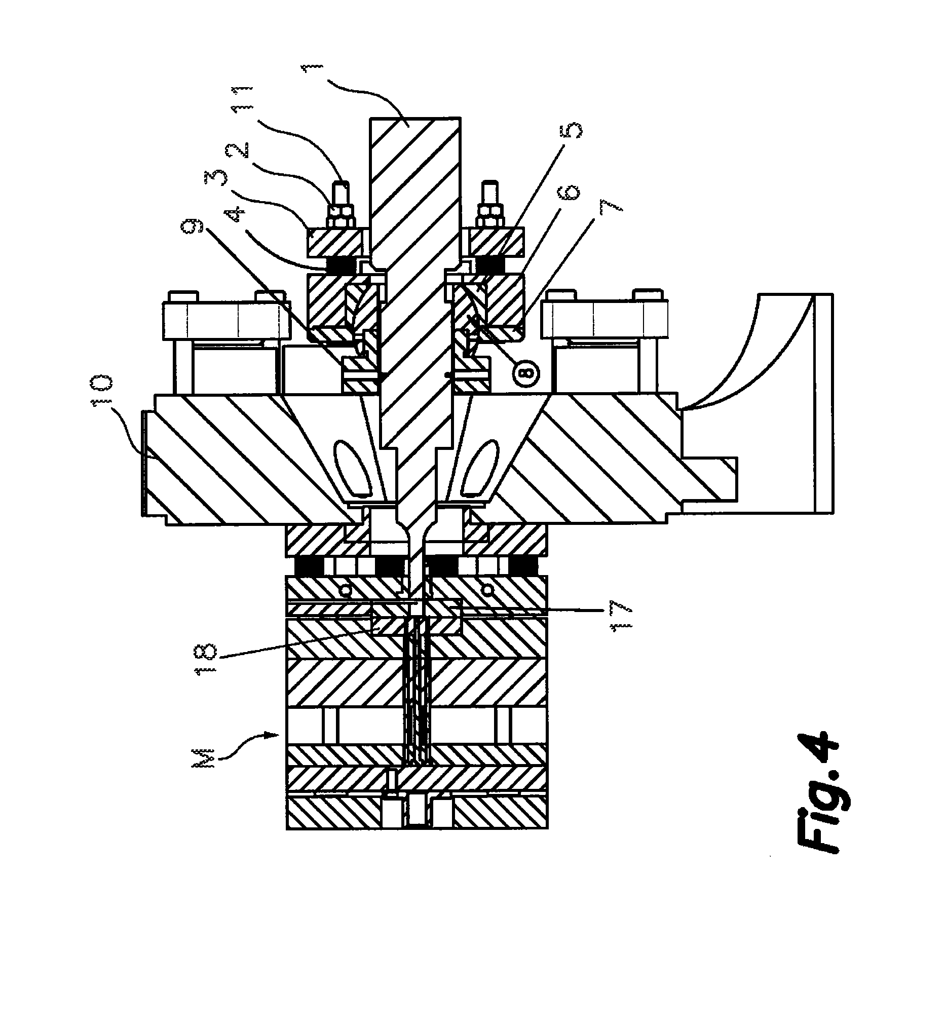
[0033]The present invention provides an ultrasonic device for molding micro parts using structural and functional concepts for molding plastics which allow simplifying both the structure of the installation and the process and maintenance thereof.

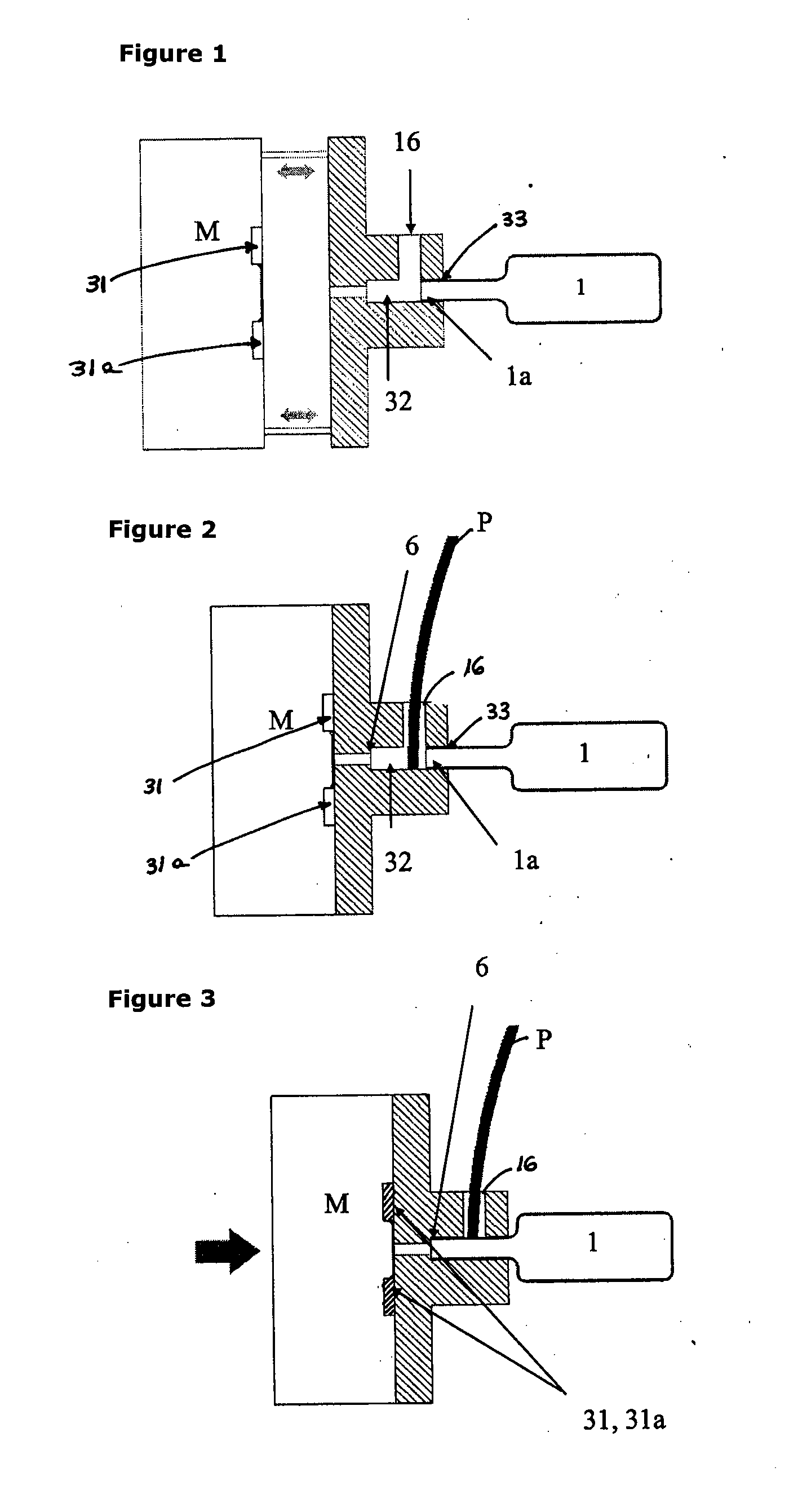
[0034]FIG. 1 shows the device for molding micro parts with the mold M open. This is the situation prior to the melting of the plastic material, in which the imprints and / or the mold can be switched at will depending on the type of part to be manufactured. The device is located in a position in which the inlet of the cavities 31, 31a of the mold M are not connected to the outlet of the chamber 32, having the tip 1a of the sonotrode inserted. This figure shows a mold M with two mold cavities 31, 31a intended for forming two parts, the number of parts added to the mold M being variable; a chamber 32 separated a certain distance from the mold M and an ultrasonic vibration element or sonotrode 1 known in and of itself. This is the situation prio...


PUM

PropertyMeasurementUnit
weightaaaaaaaaaa
weightsaaaaaaaaaa
pressureaaaaaaaaaa

Abstract

The invention relates to an ultrasonic device for molding micro plastic parts, which combines: a) a mold cavity configured in a mold having an inlet for supplying plastic material to a chamber with an access opening and the chamber facing the cavity at a distal end in relation to its access opening; b) a cantilevered ultrasonic vibration element associated with an ultrasound generator, with an end portion or tip inserted tightly into the chamber through the access opening in an axially centered manner; c) a movement device for generating a relative movement between the end portion and the parts of the mold so that the end portion engages with the supplied plastic material and exerts a pressure of pre-determined magnitude thereon upon activation of the ultrasonic vibration element.

Description

FIELD OF THE INVENTION[0001]The present invention generally relates to a device for manufacturing micro parts by means of molding, which uses ultrasonic vibration as a source of energy for melting and injecting the plastic, at the same time of accessing or filling the mold cavity or cavities with the molten plastic. The plastic is supplied to the device continuously in the form of a thread or strip, or discontinuously by means of granules or microgranules.[0002]In the present specification, micro part will be understood as a plastic part having a weight less than 1 gram and generally having a range of weights comprised between thousandths of a gram to 1 gram or parts having a greater weight with defined microstructural details.[0003]The present invention belongs to the chemical industry sector, specifically the field of transforming plastics by molding.BACKGROUND OF THE INVENTION[0004]There is an entire market today which requires parts with weights less than 1 g or with greater wei...

Claims


Application Information

Patent Timeline
Patent Type & Authority Applications(United States)
IPC IPC(8): B29C35/08
CPCB29B13/022B29B13/023B29C35/0261B29C45/021B29C2045/0098B29C45/461B29C45/462B29C45/531B29C2045/0094B29C45/46B29C2791/008B29C33/06B29C45/56
Inventor PLANTA TORRALBA, FRANCISCO JAVIERESCUDERO MARTINEZ, ENCARNACIONSANCHO DESCALZO, ANDRESMACIAS LOPEZ, PEDRO LUISBAS FERRERO, JOSE FERNANDORODRIGUEZ SIERRA, EUGENIAPULIGA, FRANCESCO
Owner ULTRASION SL
Why Eureka
Try Eureka