
Fine blanking press and method for operating the same

a technology of fine blanking press and operation method, which is applied in the direction of presses, metal-working feeding devices, manufacturing tools, etc., can solve the problems of high press power consumption, unsatisfactory secondary effects, and large cooling unit, so as to improve the accuracy of geometry and reduce energy consumption , the effect of prolonging the tool li

Pending Publication Date: 2020-06-18
PETER WOLTERS GMBH
View PDF2 Cites 5 Cited by
  • Summary
  • Abstract
  • Description
  • Claims
  • Application Information

AI Technical Summary

Benefits of technology

The patent describes a force control system for a fine blanking press that allows for fast and precise force control. The system uses pre-pressurized hydraulic fluid to control the force, and the pressure is maintained in the system without the need for a rebuilding process. The system allows for movement of the press units in both directions, and the force exerted by the press units can be controlled during the movement process. The force control system also allows for a blanking process that reduces blanking stress and improves part quality. The system is flexible and efficient, and can be used with different parts and functions during the press cycle.

Problems solved by technology

However, undesired secondary effects are associated with this type of fine blanking press.
This in turn leads to higher press power consumption.
This in turn requires bigger cooling units and again additional power consumption.
This can lead to the process material losing flatness.
This again leads to an even higher necessary press ram force and higher power consumption.
The locking of the process material also leads to higher tool working temperature, higher tool component stress due to higher forces applied in higher temperature, tools having to support higher forces, and a risk of tool damage due to higher tool stress.
Generally, tool components are subjected to higher wear and tool life is reduced.
Tool maintenance intervals are accordingly shorter which increases costs and decreases productivity.
Further, lubrication needs to be increased due to higher friction values during the fine blanking process.

Method used


Image

  • Fine blanking press and method for operating the same
  • Fine blanking press and method for operating the same
  • Fine blanking press and method for operating the same

Examples


Embodiment Construction

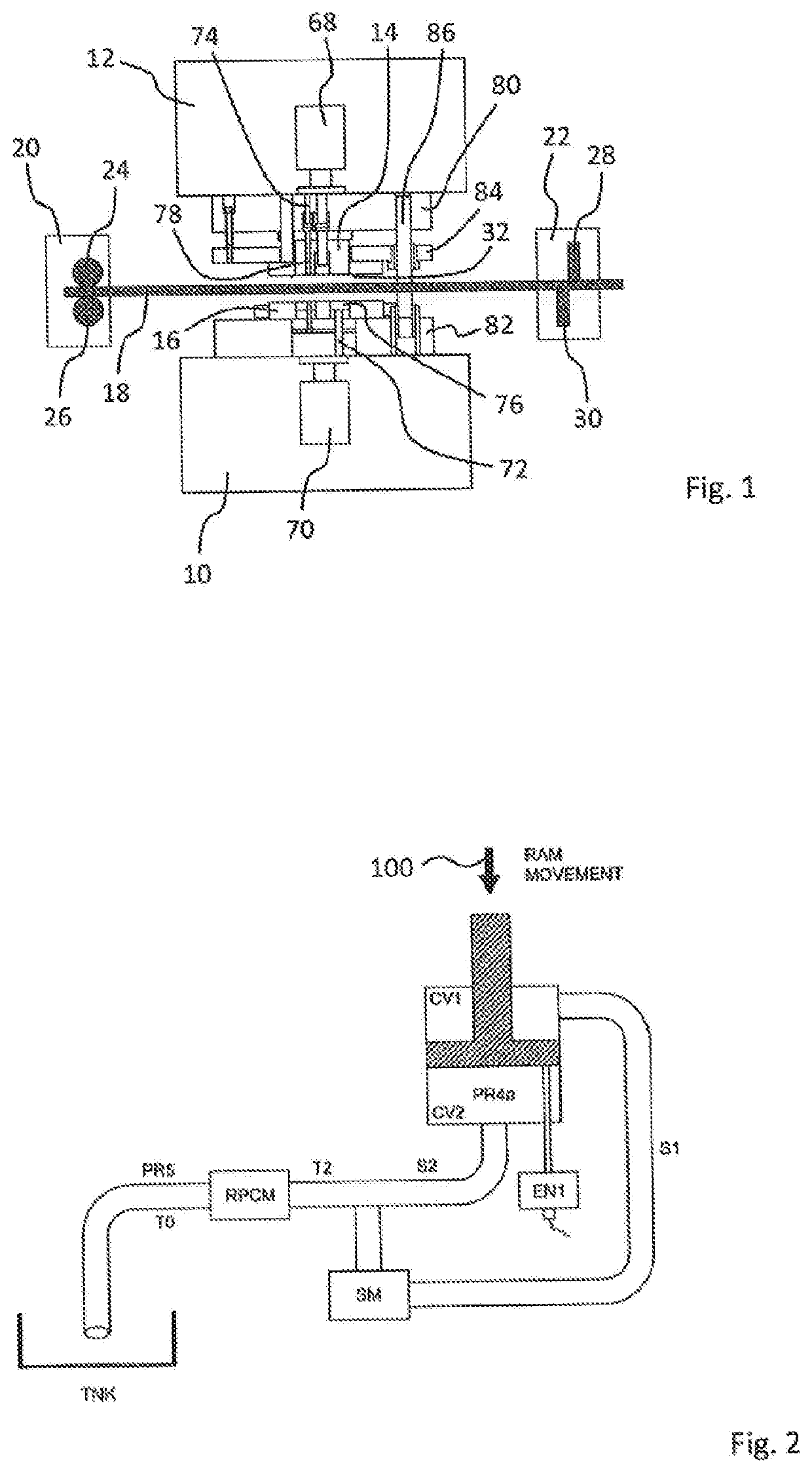
[0061]The fine blanking press according to the disclosure shown in FIG. 1 comprises a press ram 10, constituting a first press unit, and a working table 12 arranged opposite the blanking ram 10. A first press drive not further shown in FIG. 1 is provided for driving the press ram 10 in a first driving movement during a fine blanking process step, in FIG. 1 upwards and downwards. Integrated into the press ram 10 and the working table 12 are cushions 68, 70, which are connected to a blanking tool arranged between the press ram 10 and the working table 12 through transfer pins 72, 74. The blanking tool further comprises press punch 14, which may be positionally fixed together with the working table 12, and die 16, and moves together with the press ram 10. The blanking tool further comprises ejectors 76, 78, set plates 80, 82, press plate 84 and a tool guiding 86. Punch 14 and die 16 blank parts out of a sheet metal 18 fed to the process zone between the press ram 10 and the working tab...


PUM

PropertyMeasurementUnit
speedaaaaaaaaaa
forceaaaaaaaaaa
forcesaaaaaaaaaa

Abstract

The disclosure pertains to a fine blanking press comprising a first press unit comprising a first press drive for driving the first press unit in a first driving movement during a fine blanking process step, and a second press unit wherein the second press unit is driven in a second driving movement at least partially during the first driving movement of the first press unit, and wherein a force control unit exerts a counter force against a force exerted by the first press unit during its first driving movement, and wherein the force control unit comprises at least one sensor and a controller operative to receive measuring data collected by the at least one sensor, and wherein the controller is configured to carry out a closed loop control on basis of the received measuring data. The disclosure further pertains to a method for operating a fine blanking press.

Description

CROSS REFERENCE TO RELATED DISCLOSURE[0001]This application is based upon and claims priority to, under relevant sections of 35 U.S.C. § 119, European Patent Application No. 18 212 195.4, filed Dec. 13, 2018, the entire contents of which are hereby incorporated by reference.BACKGROUND[0002]Fine blanking presses allow blanking parts for example from sheet metal with high quality and flexibility with regard to the design of the parts. Fine blanking presses usually comprise a press ram and a counter unit, such as a working table, arranged opposite the press ram. A blanking tool is arranged between the blanking ram and the working table. The blanking tool can comprise, for example, one or more press plates, or ejectors, directly connected by transfer pins, to a press cushion of the press ram. Alternatively a press cushion of the working table connected to any other cushion or actuator integrated within the tool itself may be used in combination with one or more press punches or press di...

Claims


Application Information

Patent Timeline
Patent Type & Authority Applications(United States)
IPC IPC(8): B21D28/00B21D28/34
CPCB21D28/34B21D28/002B21D24/14B21D28/16B21D28/20B30B15/16B30B15/18B30B15/22B21D43/09B21D45/02B21D24/02B30B15/0064
Inventor LOZANO BONET, JOSE
Owner PETER WOLTERS GMBH
Learn More