Riser wireless communications system

a wireless communication and wireless technology, applied in the direction of transmission, electrical equipment, surveillance, etc., can solve the problems of difficult to determine the exact location of the end of the string, and do not offer the opportunity to communicate through the riser, so as to reduce the field, increase the loop area, and high permeability

Inactive Publication Date: 2013-12-19
WFS TECH
View PDF4 Cites 5 Cited by
  • Summary
  • Abstract
  • Description
  • Claims
  • Application Information

AI Technical Summary

Benefits of technology

[0012]In this way, data is transferred through the riser. This removes the requirement to have communication links up the string. Additionally, if the location of the second device is known, the location of the first device is known when a signal is detected.
[0015]Preferably, the second transceiver is arranged to transmit electromagnetic signals and the first transceiver is arranged to receive electromagnetic signals. In this way, bi-directional communication is achieved.
[0016]Preferably, the first transceiver comprises an electric field coupled antenna. Preferably also the second transceiver comprises an electric field coupled antenna. In this way, the antenna can be located inside the device, embedded in the housing of the device or mounted in a plug located on the device and does not significantly increase the size of the device or interfere with the running of the string.
[0021]Preferably the second device is located adjacent the riser towards the wellhead. In this way, conditions in the wellhead can be monitored and / or operations can be carried out at the wellhead by transmission of signals between the devices.
[0022]In an embodiment a repeater is located at the riser. In this way, the second device can be located more remote from the riser. Such an arrangement would provide for communication through a buoyancy tank which may be mounted on the riser.

Problems solved by technology

Due to the great distances which can be involved in both water depth and well depth, it can be difficult to determine the exact location of the end of the string and thus the location of tools and devices mounted on the string.
While this describes a data communication system which operates along a riser, it does not offer the opportunity to communicate through the riser to a device located on a tubular string within the riser.

Method used


Image

  • Riser wireless communications system
  • Riser wireless communications system
  • Riser wireless communications system

Examples


Embodiment Construction

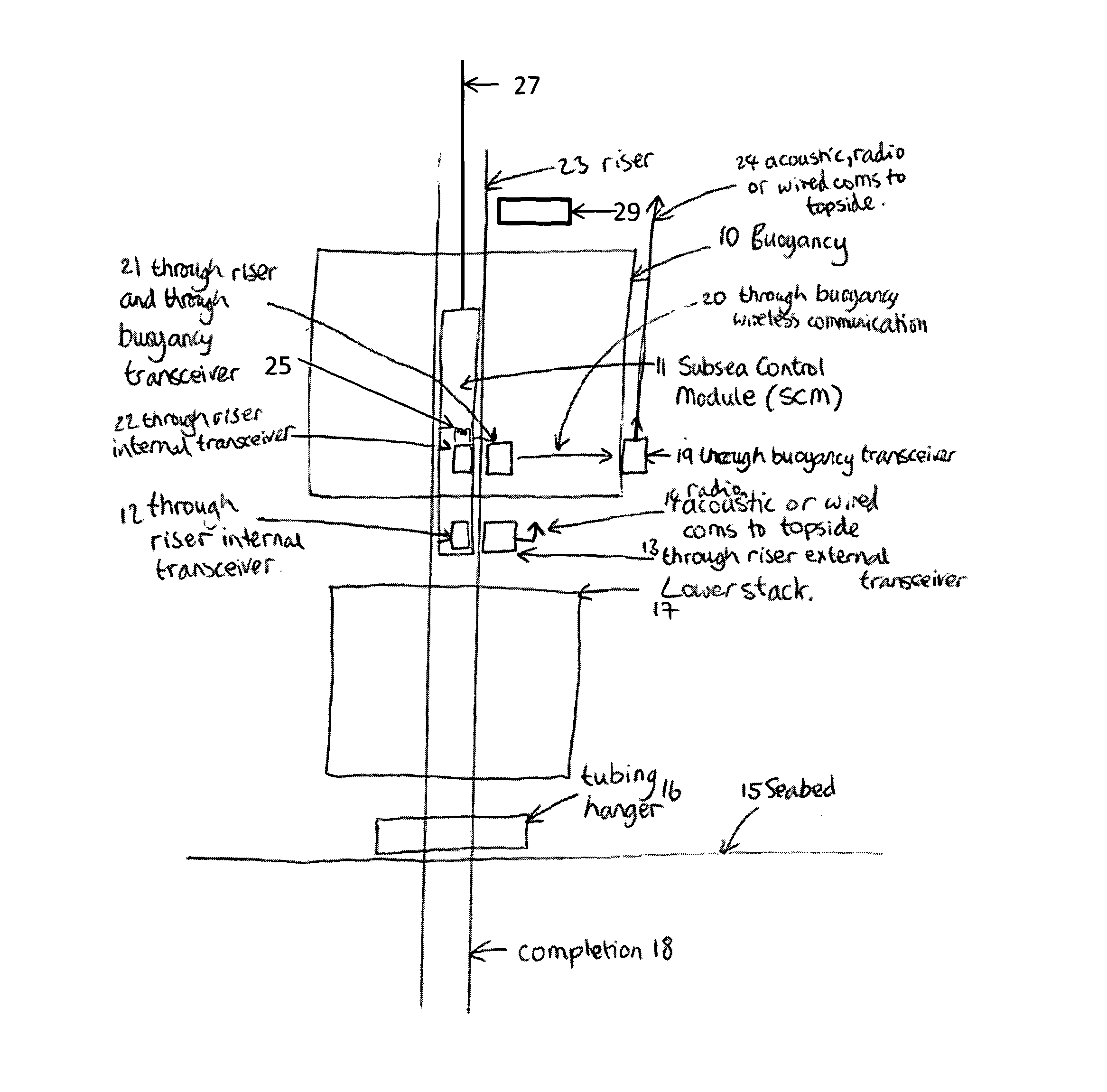
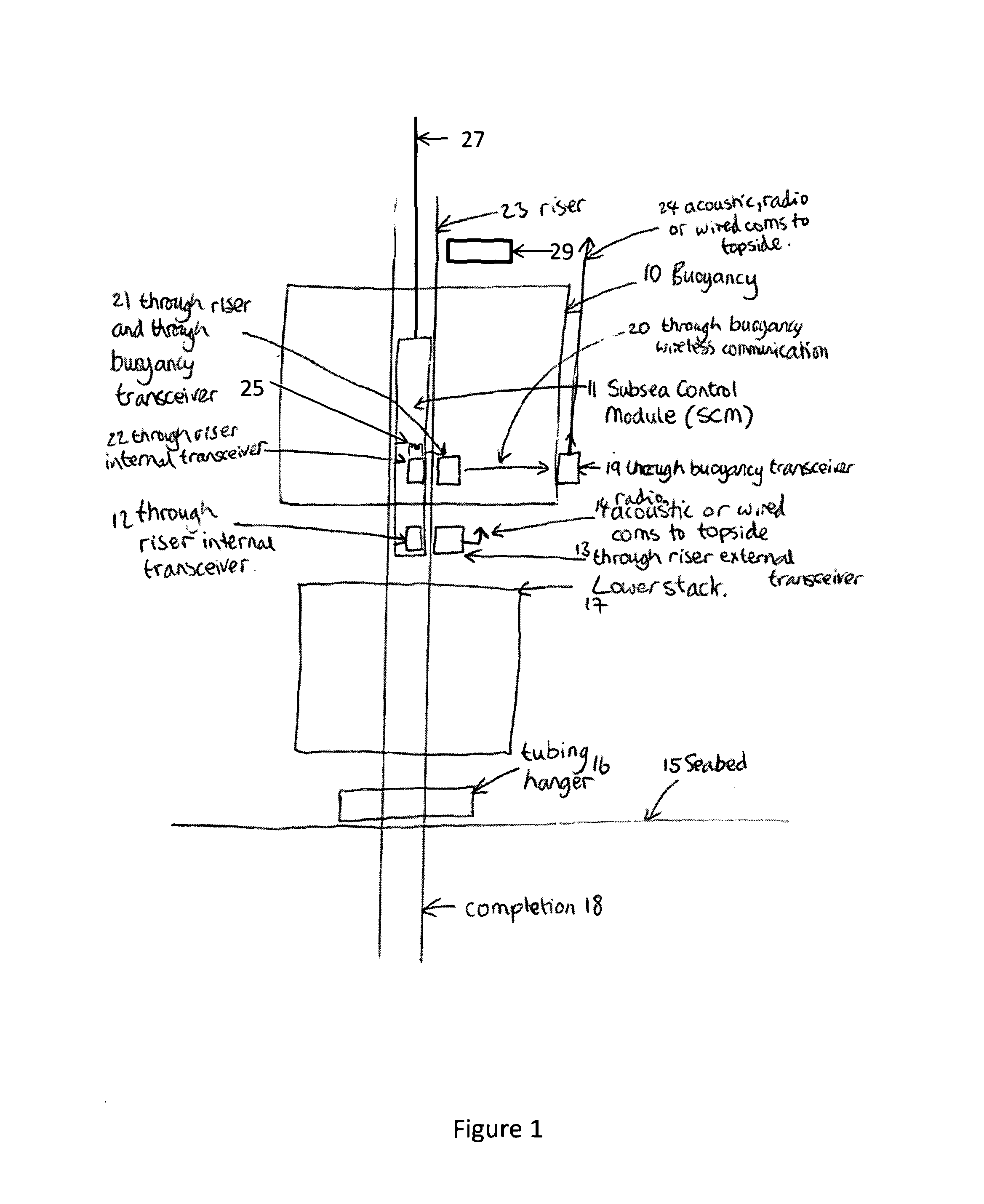
[0038]FIG. 1 shows a transceiver system deployed to communicate through a riser pipe to a transceiver deployed outside of the riser pipe in one embodiment of the present invention. Riser pipe 23 runs from a production platform through the sea to the seabed 15 and penetrates the seabed at completion 18. Subsea Control Module 11 requires relay of data from integrated sensors to a transceiver outside of the pipe structure and communication of control commands from outside the pipe structure. Transceiver 22 communicates through the pipe wall with transceiver 21 which is embedded inside buoyancy tank 10. Transceiver 21 then relays communications signals to a further transceiver 19 which is external to the buoyancy tank. Transceiver 19 is in communications with a control centre via communications link 24 which is implemented using radio communications, acoustic signalling or a direct conductive wired link. In sections of the riser which are not enclosed by buoyancy tank 10 transceiver 12 ...


PUM


Abstract

The present invention discloses a wireless data command, control and instrumentation system for deployment within a subsurface hydrocarbon production system. Low frequency magnetic signalling is used to communicate from a first transceiver deployed inside a riser pipe to a second transceiver positioned outside the riser pipe. In some embodiments data is related to a control centre. Through pipe communications may be bi-directional.

Description

FIELD OF USE[0001]The present invention relates to the field of underwater exploration, hydrocarbon extraction facilities and plants, general underwater installations and other underwater and deep-sea applications.DESCRIPTION OF THE RELATED ART[0002]A typical hydrocarbon extraction facility comprises the following: a topside rig, which is located on the surface of the sea; a wellhead, where hydrocarbons are extracted from a well buried in the seabed; a production riser which connects from the wellhead on the seabed to the topside rig and which acts as a conduit for fluids between the rig and the wellhead; an umbilical which runs along the riser and which provides power and control of the well head from a control station in the topside rig. Similarly, a hydrocarbon drilling facility comprises a topside rig or drilling vessel; a wellhead installation, providing drilling access to a well buried in the seabed; a drilling riser which connects from the wellhead on the seabed to the topsid...

Claims


Application Information

Patent Timeline
Patent Type & Authority Applications(United States)
IPC IPC(8): H04B13/02E21B47/12
CPCH04B13/02E21B17/01E21B17/028E21B47/04E21B47/09E21B47/13
Inventor CONWAY, GARETH ANTHONY JOHNVOLANTHEN, MARKHYLAND, BRENDAN
Owner WFS TECH
Why Eureka
Try Eureka