Electrical connector for fuel cell stack voltage monitoring

a technology of electric connectors and fuel cells, applied in the direction of electrochemical generators, coupling device connections, instruments, etc., can solve the problems of manifold disadvantages of such connectors, long manufacturing process, and long distances between the teeth of electric contacts

Active Publication Date: 2022-10-04
POWERCELL SWEDEN AB
View PDF21 Cites 0 Cited by
  • Summary
  • Abstract
  • Description
  • Claims
  • Application Information

AI Technical Summary

Benefits of technology

[0007]It is therefore desirable to provide an electric connector, which can be easily fixed to the fuel cell stack and allows for a flexible monitoring of the fuel cell stack voltage.
[0017]According to a further embodiment, the plug and the at least two units are connected via conductive paths bonded into a flexible plastic material. As a flexible plastic material is used, a variable positioning of the units and the plug with respect to each other may be achieved as the connection may be easily bent.
[0019]The plug may be adapted to provide an analog signal, i.e. a signal from the contact pins, to the cell voltage measurement system. In the cell voltage measurement system, the analog signal may be analyzed and a result of the analyzation may be provided as a digital signal to any further processing or computing unit. The analog signal as provided via the plugs may be transmitted via a bus or the like to the cell voltage measurement system. Thus, the analyzation and further processing, which is carried out in the cell voltage measurement system may be located remote. This provides the advantage that no space for the cell voltage measurement is required in the fuel cell stack. Further, the heat generation may be reduced at the fuel cell stack.
[0021]The attaching elements may provide a variable positioning of the plug as they may be attached to the holding element at variable positions. This may be realized for example using self-tapping screws which can be attached to the housing without a need for holes.
[0022]According to a further embodiment, the pins of one unit are arranged in at least two rows. This means that two consecutive pins are arranged in two different rows and are thus offset to each other. This may provide the advantage that the cells may be designed very thin. As the pins are offset to each other, they may contact the cells without contacting each other. Thus, short circuiting may be avoided.
[0023]Preferably, the pins of one unit are arranged in three rows. Therefore, three consecutive pins are arranged in three different rows and are thus offset to each other. This allows for even thinner plates.

Problems solved by technology

The disadvantage of such a connector is manifold.
Secondly, the electric connector easily detaches from the bipolar plates, so that additional fixing elements are required for fixing the electric connector to the fuel cell stack.
A further problem is that the distances between the teeth of the electric contact must be carefully designed in order to fit to the fuel cell stack.
Thereby, only minimal manufacturing tolerances are allowed, which in turn results in a costly and time-consuming manufacturing process.
Thus, plates may not be easily skipped.
However, this causes a wrong measurement as a correct voltage may be measured only with reference to the previous plate.
The overall assembly of electric connector and printed circuit board may thus be insensitive to fine tolerances.

Method used


Image

  • Electrical connector for fuel cell stack voltage monitoring
  • Electrical connector for fuel cell stack voltage monitoring
  • Electrical connector for fuel cell stack voltage monitoring

Examples


Embodiment Construction

[0038]In the following same and similar functioning elements are indicated with the same reference numerals.

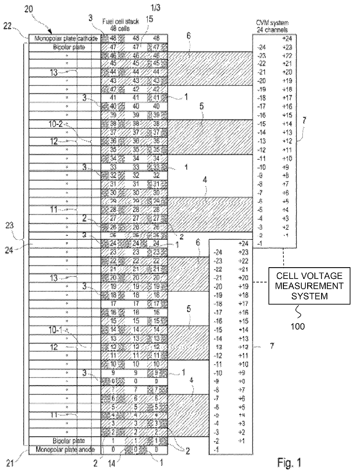
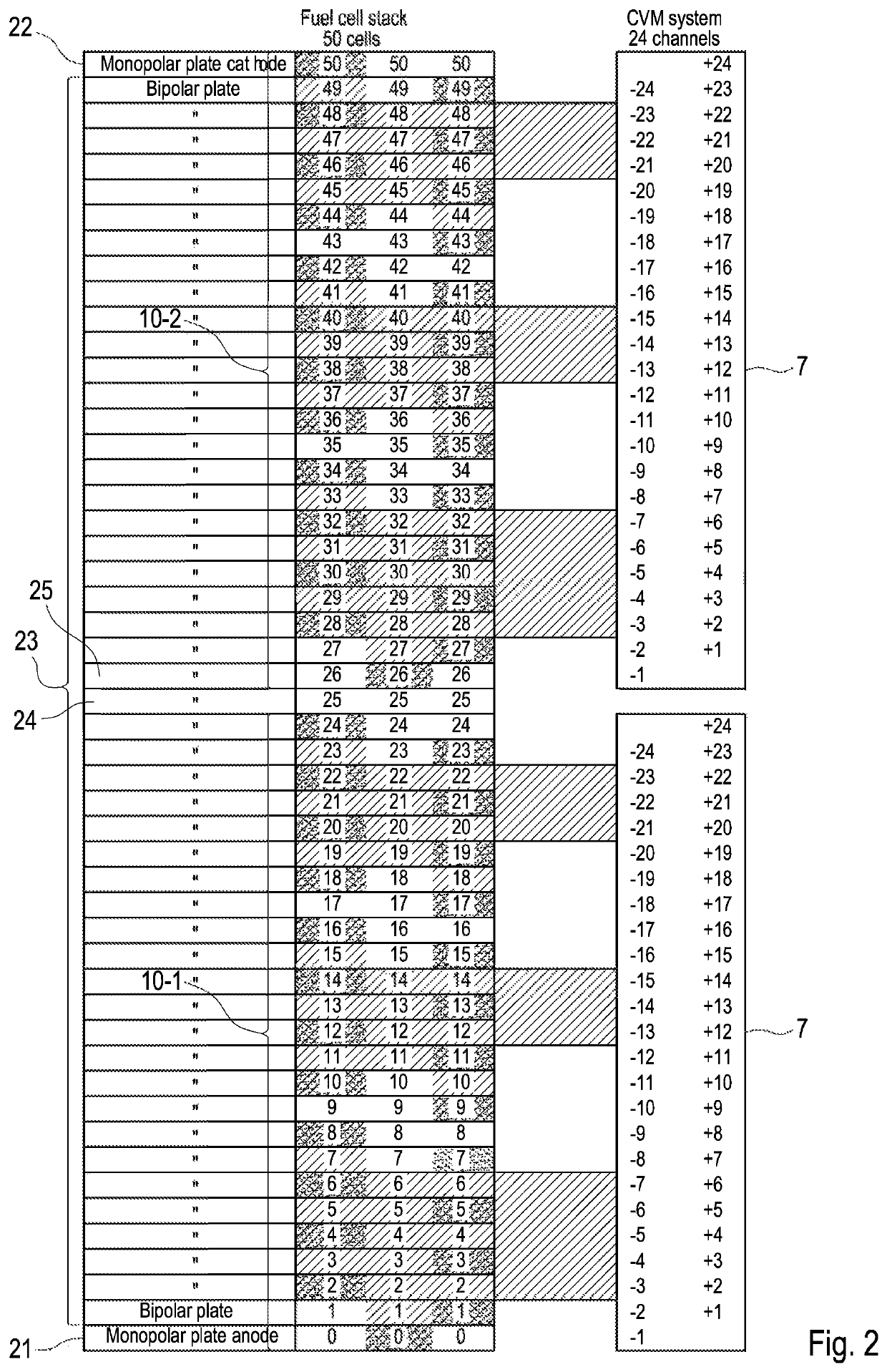
[0039]FIGS. 1 and 2 show two schematic views of a fuel cell stack 20 with two electric connectors 10 (10-1, 10-2). The fuel cell stack 20 comprises a plurality of bipolar plates 23, sandwiched between two monopolar plates 21 (anode) and 22 (cathode). The plates 21, 22, 23 are also referred to as fluid flow field plates.

[0040]For electrically contacting the plates 21, 22, 23 of the fuel cell stack 20, an electric connector 10 is provided. In the embodiments illustrated in FIGS. 1 and 2, each electric connector 10-1, 10-2 contacts 25 plates. However, any other number of plates may be possible.

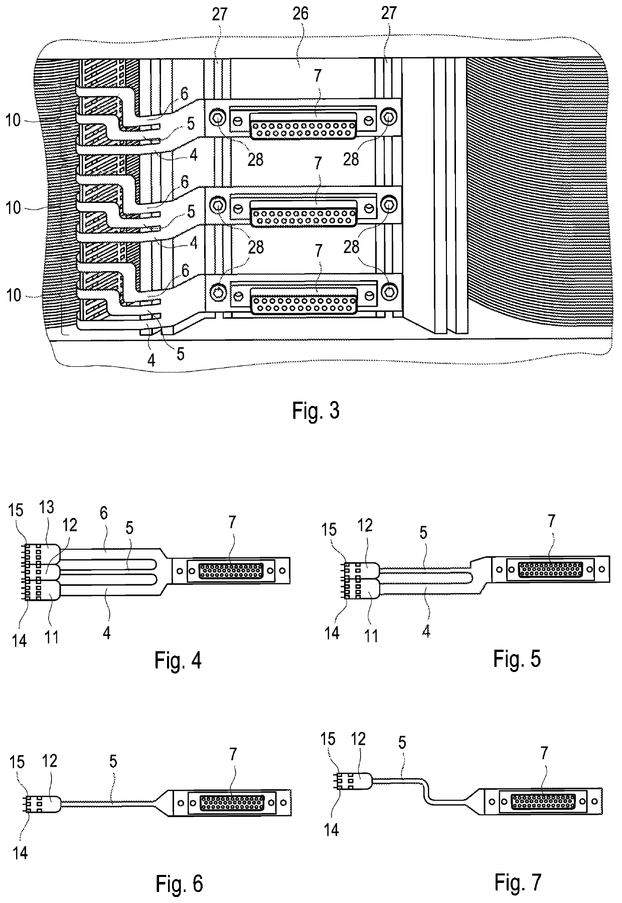
[0041]Each electric connector 10-1, 10-2 comprises three units 11, 12, 13. Each unit 11, 12, 13 comprises a plurality of contact pins 1, 2, 3 which contact the plates 21, 22, 23. Each unit 11, 12, 13 is connected via conductive paths 4, 5, 6 to a plug 7.

[0042]A first pin 1 of each of the un...


PUM

PropertyMeasurementUnit
flexibleaaaaaaaaaa
voltageaaaaaaaaaa
stack voltageaaaaaaaaaa

Abstract

An electric connector for fuel cell stack voltage monitoring includes at least two separate units, each unit including a plurality of pins, each pin being adapted to contact a plate of the fuel cell stack for monitoring a fuel cell stack voltage. The first pin of each unit is adapted to provide a measurement of a reference voltage.

Description

BACKGROUND AND SUMMARY[0001]The present invention relates to an electric connector for fuel cell stack voltage monitoring. Further, the present invention relates to an electric connector arrangement comprising at least two of these electric connectors. Moreover, the present invention relates to a fuel cell stack arrangement comprising such an electric connector. Furthermore, the present invention relates to a method for fuel cell stack voltage monitoring.[0002]A fuel cell stack is usually formed by stacking a large number of unit cells into numerous layers. Each of the unit cells comprises at least a membrane electrode assembly (MEA) having an ion exchange membrane sandwiched between an anode and a cathode, and fluid flow field plates on both outer sides of the MEA. Through the fluid flow field plates, hydrogen fuel and an oxidizing agent are supplied to the MEA, which generates electric power.[0003]For such a fuel cell stack, management of the power generation state of each unit ce...

Claims


Application Information

Patent Timeline
Patent Type & Authority Patents(United States)
IPC IPC(8): G01R1/44H01M8/04537G01R31/396G01R31/3835H01M8/0258H01R31/00
CPCH01M8/04552G01R31/3835G01R31/396H01M8/0258H01M8/04559H01R31/005H01R2201/20H01R13/6683Y02E60/50G01R1/073H01M8/2465H01M8/04298G01R19/16542G01R31/36H01R13/02H01M8/02H01M8/0297H01M8/04537H01M8/1004H01M8/24H01M8/2404H01M8/249
Inventor MUNTHE, STEFANHOLMBERG, MATTIAS
Owner POWERCELL SWEDEN AB
Why Eureka
Try Eureka