Modular structural composite beam

a technology of structural beams and beams, applied in the direction of girders, final product manufacture, machines/engines, etc., can solve the problem of limited options for structural beam design modification, and achieve the effect of improving design flexibility, quality, and design flexibility

Active Publication Date: 2013-12-26
BLADE DYNAMICS LTD
View PDF12 Cites 7 Cited by
  • Summary
  • Abstract
  • Description
  • Claims
  • Application Information

AI Technical Summary

Benefits of technology

[0011]A design for a modular wind turbine blade is described in the applicant's published International patent application WO 2009 / 034291. This application discloses a wind turbine blade which comprises a plurality of standardised component parts which allow for greater design flexibility, for the blade as a whole, than traditional manufacture techniques. However, it only provides limited options for modification of the structural beam design. It is an aim of the present invention to provide a modular structural composite beam which provides improved design flexibility and quality and which can be used as part of a traditional wind turbine blade, as part of a modular wind turbine blade, or in other structural applications such as bridges.

Problems solved by technology

However, it only provides limited options for modification of the structural beam design.

Method used


Image

  • Modular structural composite beam
  • Modular structural composite beam
  • Modular structural composite beam

Examples


Embodiment Construction

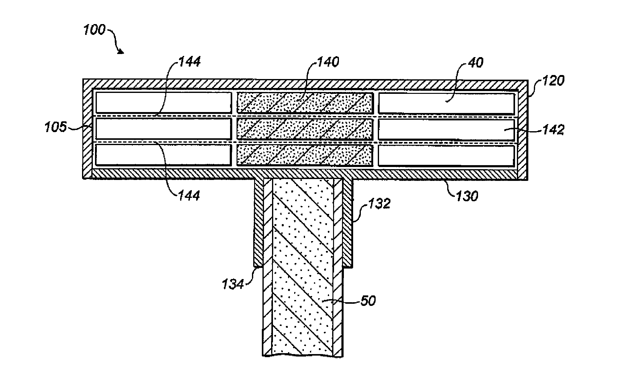
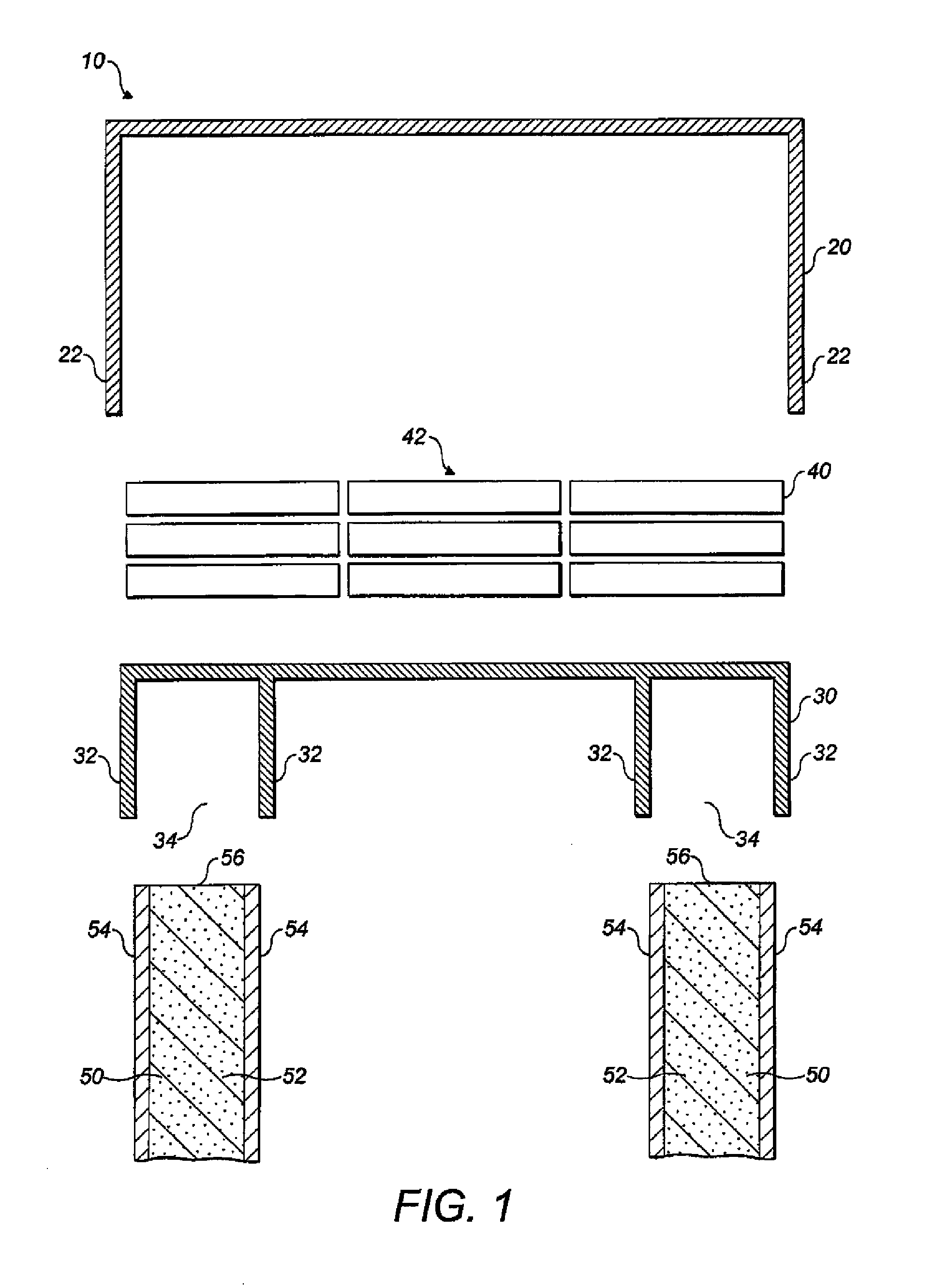
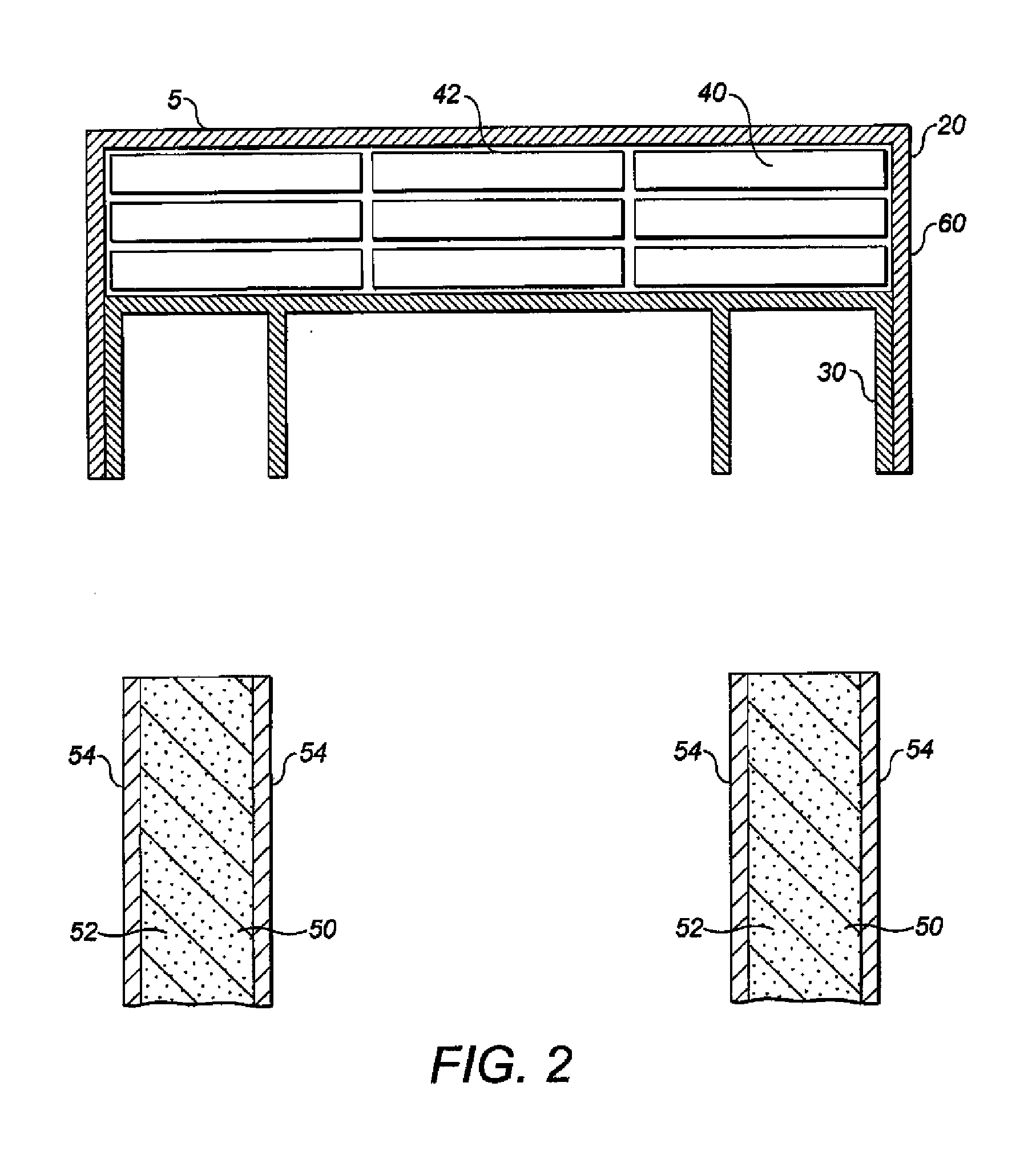
[0035]FIG. 1 shows an exploded schematic view of a section of a modular structural composite beam 10. The beam 10 comprises first 20 and second 30 skin elements and a plurality of elongate elements 40. In addition, the beam 10 comprises two shear webs 50 each comprising a structural core 52 and outer skin layers 54.

[0036]The structural cores 52 may be made of any suitable material including PVC, PET, balsa wood or STYROFOAM or other structural core material widely known and used in the art. The outer skin layers 54 comprise predominantly multiaxial (±45°) fibre reinforced plastic. The outer skin layers 54 are attached to the cores 52 by an adhesive such as a structural adhesive (such as epoxy, polyurethane, acrylic, silicone) or with a resin such as a polyester, vinylester, epoxy or other structural thermosetting or thermoplasic resin.

[0037]The elongate elements 40 comprise predominantly uniaxial fibre reinforced plastic. The elongate elements are typically ‘preformed’ unidirectiona...


PUM

PropertyMeasurementUnit
lengthaaaaaaaaaa
dimensionsaaaaaaaaaa
mechanical propertiesaaaaaaaaaa

Abstract

A modular fibre reinforced plastic flange for a structural composite beam which comprises a body formed of a plurality of elongate elements arranged in an array, wherein the dimensions of the body are substantially determined by the number and arrangement of the elongate elements in the array, and a skin member at least partially surrounding the array. Also, a structural composite beam comprising the modular fibre reinforced plastic flange and a shear web connected to the skin member of the modular flange. A method of making the modular flange and beams, and a kit of parts for making the modular flange are also disclosed.

Description

CROSS-REFERENCE TO RELATED APPLICATIONS[0001]This application is a continuation of U.S. patent application Ser. No. 13 / 663,296, filed on Oct. 29, 2012, and entitled “A MODULAR STRUCTURAL COMPOSITE BEAM,” which is a continuation of Patent Cooperation Treaty International Patent Application PCT / GB2011 / 000661, filed Apr. 28, 2011, and entitled “A MODULAR STRUCTURAL COMPOSITE BEAM,” which is incorporated by reference herein in its entirety, and which claims priority to Great Britain Patent Application 1007336.9, filed on Apr. 30, 2010.BACKGROUND OF THE INVENTION[0002]1. Field of the Invention[0003]The present invention relates to a modular structural composite beam. In particular, the present invention relates to a modular structural composite beam for use in a wind turbine blade.[0004]2. Description of the Related Art[0005]Large wind turbine blades (>35 m in length) are typically constructed by forming a strengthening and stiffening cantilever beam or box spar inside an aerodynamic ...

Claims


Application Information

Patent Timeline
Patent Type & Authority Applications(United States)
IPC IPC(8): E04C3/29
CPCE04C3/29B29C70/865B29D99/0003B29K2105/24B29K2105/243B29L2031/003B29L2031/082F03D1/065F05B2280/6003F05B2280/6013F05B2280/702F05C2253/04F05C2253/16F05C2253/22Y10T29/49826Y10T29/49616Y02E10/72Y02P70/50
Inventor HAYDEN, PAUL TREVORBEHMER, HARALD
Owner BLADE DYNAMICS LTD
Why Eureka
Try Eureka