
Device for the temporary position fixing of aircraft structures to be interconnected

a technology for fixing aircraft structures and adjacent positions, which is applied in the direction of aircraft assembly, manufacturing tools, and clamps, etc., can solve the problems of long throughput times and considerable work effort in the manufacture of fuselages, and achieve the effect of effectively protecting the sensitive outside surface of the aircraft structure from damag

Inactive Publication Date: 2013-12-26
AIRBUS OPERATIONS GMBH
View PDF5 Cites 24 Cited by
  • Summary
  • Abstract
  • Description
  • Claims
  • Application Information

AI Technical Summary

Benefits of technology

The present invention provides a device for temporary position fixing of adjacent aircraft structures that requires minimal external energy supply lines. This device prevents drill chippings from entering between connecting plates during manufacturing and simplifies the process of aligning adjacent components. It also eliminates the need for moving apart and cleaning of the aircraft structures prior to connection, resulting in significant savings in manufacturing time. The device has the added advantage of being able to operate using pneumatic cylinders for higher automation. Additionally, the invention includes the use of a sliding foot to protect sensitive surfaces of the aircraft structure from damage.

Problems solved by technology

However, since during pre-drilling for the purpose of inserting the screw-type clipping rivets no pre-stress force can be applied, after the pilot holes have been made the fuselage sections need to be separated and cleaned.
Renewed separation of the fuselage sections prior to final riveting, combined with the cleaning effort required for this step, overall results in quite considerable work effort and in long throughput times in the manufacture of fuselages.

Method used


Image

  • Device for the temporary position fixing of aircraft structures to be interconnected
  • Device for the temporary position fixing of aircraft structures to be interconnected
  • Device for the temporary position fixing of aircraft structures to be interconnected

Examples


Embodiment Construction

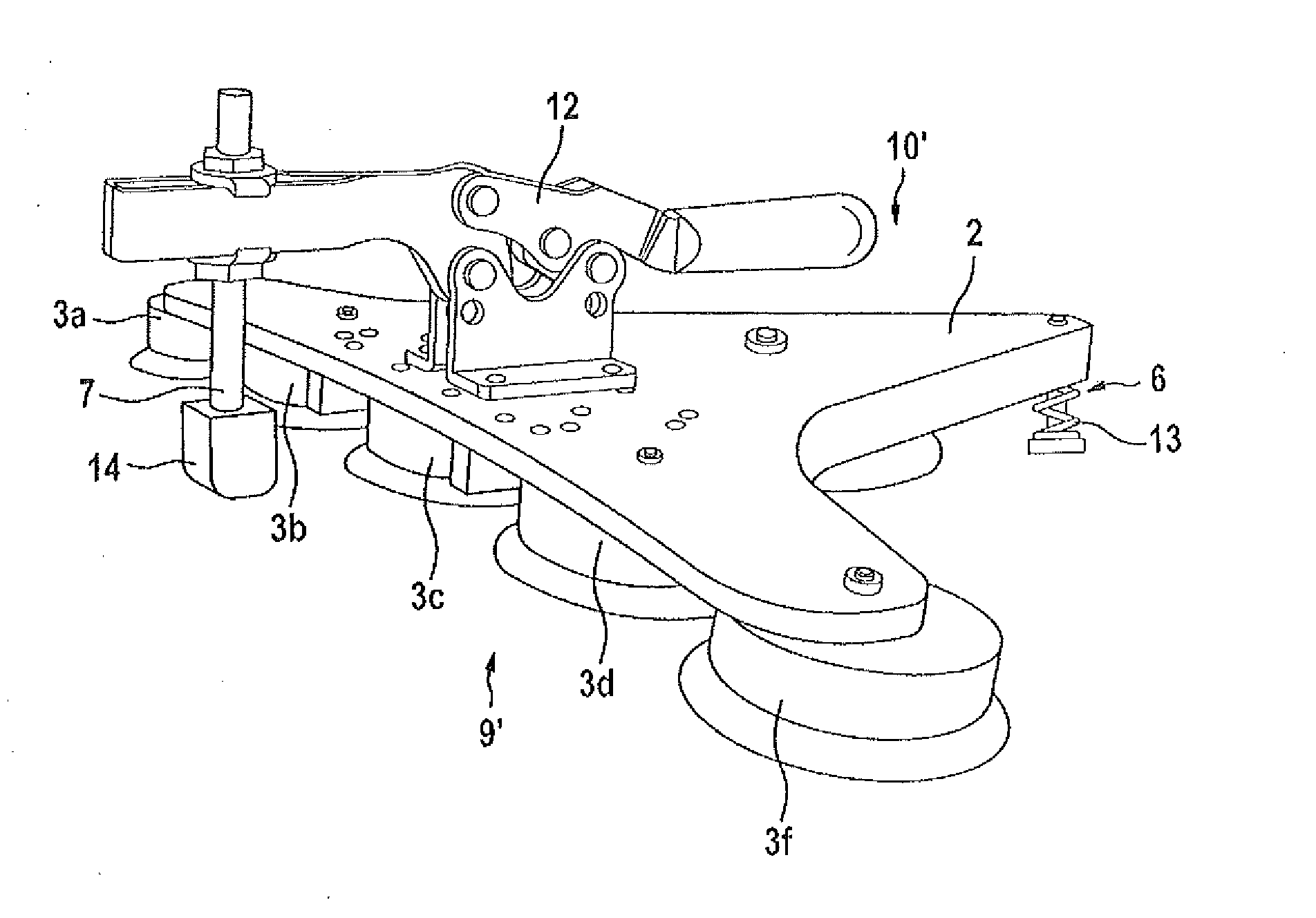
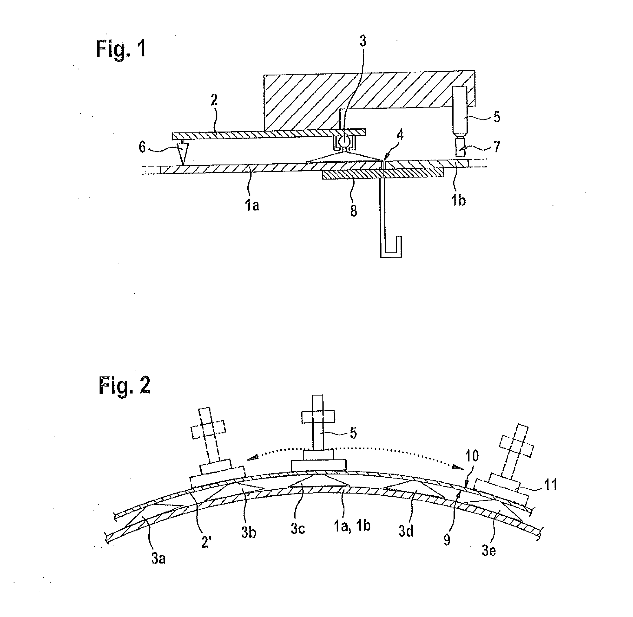
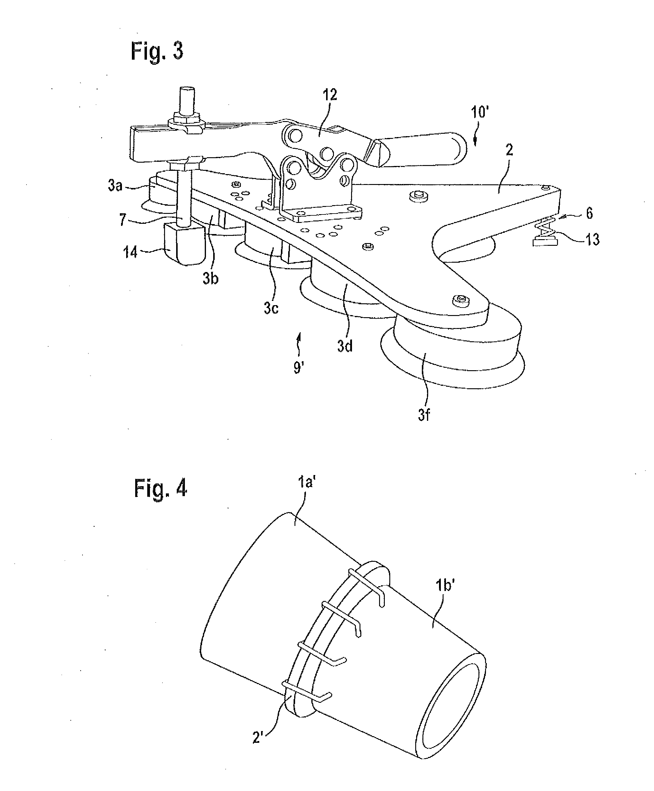
[0023]According to FIG. 1, the device for the temporary position fixing of adjacently arranged aircraft structures 1a and 1b to be interconnected comprises a support frame 2 with at least one vacuum suction cup 3 affixed in the region of a transverse gap 4 on the side of one aircraft structure 1a. At least in its edge region the aircraft structure 1a is designed so as to be considerably more rigid than the other aircraft structure 1b, which by means of the device as a result of easy deformation can be made to conform to the aircraft structure 1a.

[0024]Mechanical contact pressure means, in the present embodiment a pneumatic cylinder 5 (shown diagrammatically), are attached in a gap-bridging manner to the support frame 2 in such a manner that clamping pressure is exerted approximately perpendicularly onto the adjacent aircraft structure 1b. In order to absorb the clamping force on the side of the support frame 2, the latter comprises a counter support 6 at the end. The end of the pis...


PUM


Abstract

A device for the temporary position fixing of adjacently arranged aircraft structures to be interconnected includes a support frame with at least one vacuum suction cup for temporary surface attachment and with clamping means for the position fixing of the aircraft structures to be interconnected. The support frame with the at least one vacuum suction cup in the region of a transverse gap is attached on the side of one aircraft structure. The support frame includes mechanical contact pressure means for the gap-bridging position fixing of the adjacent other aircraft structure. On the support frame there is a counter support to pressure elements of the contact pressure means.

Description

CROSS-REFERENCE TO RELATED APPLICATIONS[0001]The present application is a continuation of International Application No. PCT / EP2012 / 053081, filed Feb. 23, 2012, which claims priority from German Patent Application No. 10 2011 012 625.2 filed Feb. 28, 2011 and claims the benefit of the filing date of U.S. Provisional Patent Application No. 61 / 447,360 filed Feb. 28, 2011, the disclosures of which are hereby incorporated herein by reference.FIELD OF THE INVENTION[0002]The present invention relates to a device for the temporary position fixing of adjacently arranged aircraft structures to be interconnected, with the device comprising a rigid support frame with at least one vacuum suction cup for the temporary surface attachment of the device to one of the adjacent aircraft structures, and with clamping means for the position fixing of the other aircraft structure to be connected by means of the aforesaid by way of a transverse gap.[0003]The field of application of the invention predomina...

Claims


Application Information

Patent Timeline
IPC IPC(8): B25B11/00
CPCB25B11/007B25B5/12B64F5/10
Inventor BENSE, ROLFGORR, EUGENSTROHBACH, TIM
Owner AIRBUS OPERATIONS GMBH
Learn More