
Local Coil for a Magnetic Resonance Imaging System and Magnetic Resonance Imaging System

Active Publication Date: 2013-12-26
SIEMENS HEATHCARE GMBH
View PDF5 Cites 13 Cited by
  • Summary
  • Abstract
  • Description
  • Claims
  • Application Information

AI Technical Summary

Benefits of technology

The patent describes a magnetic resonance imaging system that uses a wireless transmission mechanism to regulate the power, field strength, and current / voltage of the system based on the position of the patient being examined. This ensures that the supply field, which is the main source of energy for the system, does not penetrate the patient and can be controlled and limited. This feature makes it safer and more effective for medical applications. Additionally, the transmitting mechanism can include inductive technology and can be used even when there is no supply field present.

Problems solved by technology

It is problematical that immunity to these frequencies is not checked for implants so that the use of a wirelessly operated local coil for implant carriers is to be carefully considered.

Method used


Image

  • Local Coil for a Magnetic Resonance Imaging System and Magnetic Resonance Imaging System
  • Local Coil for a Magnetic Resonance Imaging System and Magnetic Resonance Imaging System
  • Local Coil for a Magnetic Resonance Imaging System and Magnetic Resonance Imaging System

Examples


Embodiment Construction

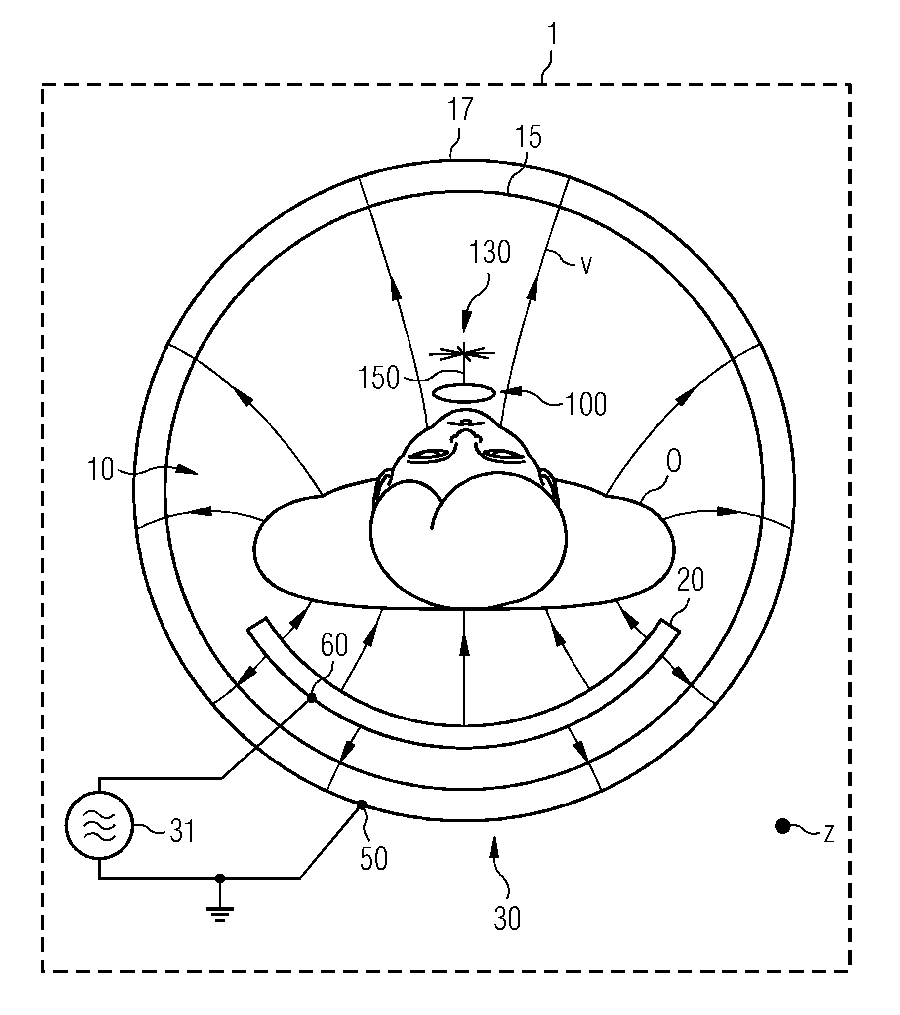
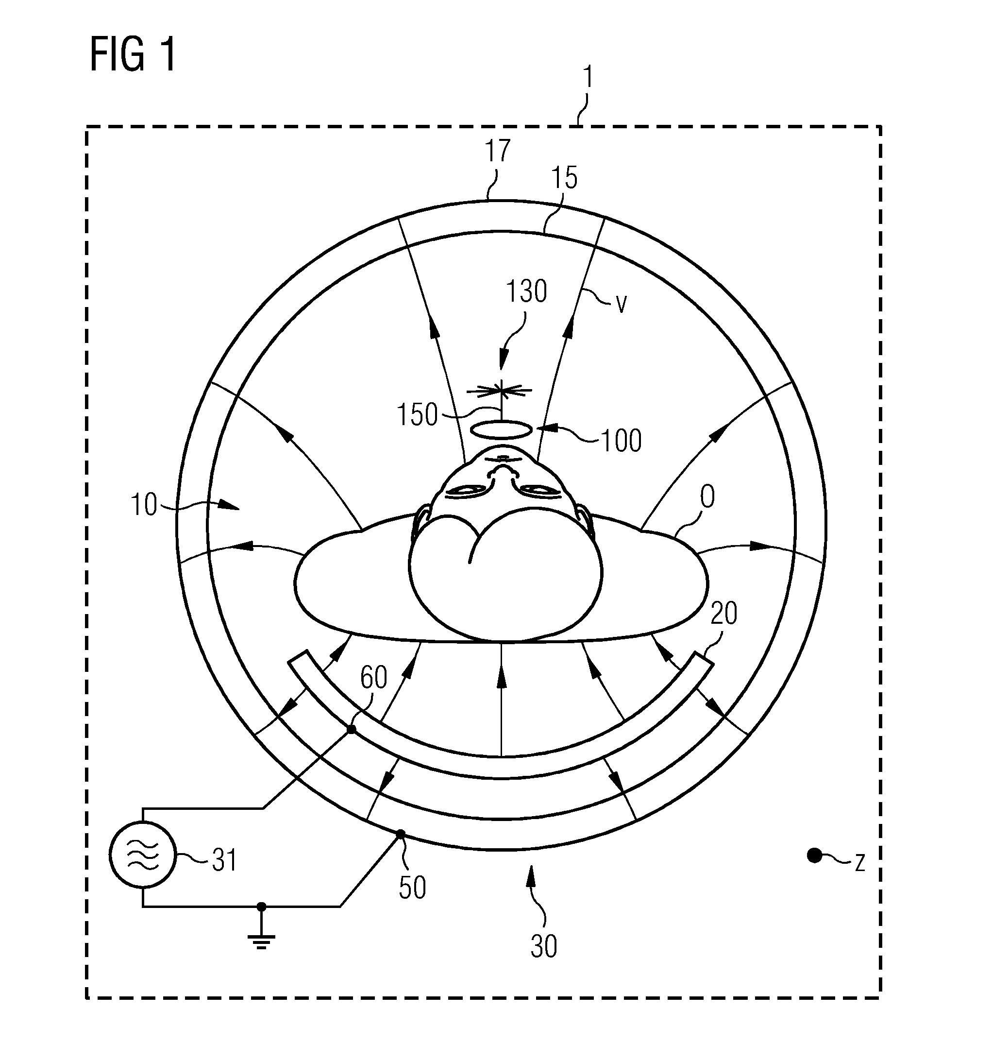
[0048]FIG. 1 is a simple block diagram of a magnetic resonance system 1 with a local coil 100 that, for example, as described in more detail with respect to FIGS. 3 to 5, may be further developed. The core of the magnetic resonance system 1 is a commercially available tomograph (e.g., a scanner), in which an object under investigation O is positioned on a patient table 20 or a bed in a cylindrical measuring chamber or patient tunnel 10 (e.g., a bore).

[0049]The magnetic resonance system 1 may also have the components described below, some of which are not shown for purposes of clarity.

[0050]Inside the tomograph, a fixed whole-body antenna arrangement, embodied, for example, as a birdcage antenna, for the emission of magnetic resonance excitation signals or optionally also for the reception of magnetic resonance signals is provided.

[0051]As FIG. 1 shows, in operation, a local coil 100, for example, is provided in the bore 10 of the tomograph of the magnetic resonance system 1. The loc...


PUM


Abstract

A local coil for a magnetic resonance imaging system for acquisition of magnetic resonance signals includes a receiving mechanism for wireless transmission of operating energy of the local coil and / or a signal of the magnetic resonance imaging system. The receiving mechanism is configured to take the operating energy and / or the signal from a supply field. A magnetic resonance imaging system is also provided. The magnetic resonance imaging system includes a transmitting mechanism for wireless transmission of operating energy of a local coil and / or a signal of the magnetic resonance imaging system. The transmitting mechanism has a transmission signal generator that is connected to a field source and a field sink. The transmitting mechanism is constructed such that, in operation, the operating energy and / or the signal is transmitted by a supply field that is present as an electrical alternating voltage field between the field source and the field sink.

Description

[0001]This application claims the benefit of DE 10 2012 210 507.7, filed on Jun. 21, 2012, which is hereby incorporated by reference.BACKGROUND[0002]The present embodiments relate to a local coil for a magnetic resonance imaging system and a magnetic resonance imaging system, where the local coil or the magnetic resonance imaging system are embodied for the wireless transmission of operating energy or a reference signal.[0003]Imaging systems based on a magnetic resonance imaging method (e.g., using nuclear spins, magnetic resonance tomography scanners) are proven in numerous applications. In this type of image acquisition, a strong static basic magnetic field B0 is used for the initial orientation and homogenization of magnetic dipoles that are to be examined. To determine material properties of an object under investigation to be depicted, the dephasing or relaxation time is determined after a deflection of the magnetization from the initial orientation so that different material r...

Claims


Application Information

Patent Timeline
IPC IPC(8): G01R33/36
CPCG01R33/3692A61B5/055G01R33/34G01R33/341G01R33/3621
Inventor VESTER, MARKUS
Owner SIEMENS HEATHCARE GMBH
Learn More